

an optical lens
A kind of optical lens and lens technology, applied in the field of optical lens, can solve the problem of low imaging quality of the optical system, and achieve the effect of wide field of vision, good visual effect and small weight
- Summary
- Abstract
- Description
- Claims
- Application Information
AI Technical Summary
Problems solved by technology
Method used
Image

Examples
no. 1 example
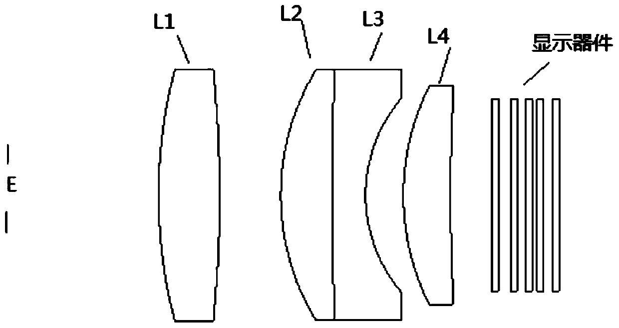
[0029] figure 1 A schematic structural diagram of the optical lens according to the first embodiment of the present invention is shown, as figure 1 As shown, from the human eye observation side to the display device side (from left to right), there are diaphragm E (where human eyes observe), the first lens L1, the second lens L2, the third lens L3, and the fourth lens L4 , the first lens L1, the second lens L2 and the fourth lens L4 are positive lenses, the third lens L3 is a negative lens, wherein the positive lens of L1 can be a positive meniscus lens or a convex lens, the second lens and The third lens constitutes a positive-negative doublet for correcting the chromatic aberration of the system. The fourth lens L4 corrects field-dependent aberrations including distortion and curvature of field.
[0030] As a guarantee for obtaining a good imaging effect under a certain aperture, it is preferable to make each lens focal length of the present invention satisfy the following...
no. 2 example
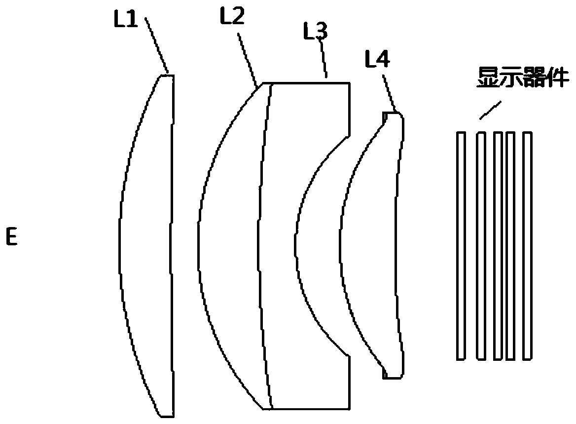
[0053] Not limited to the form that only includes 4 lenses, the optical lens among the present invention can also add the 5th lens to further improve the imaging quality of the system, adopt as Figure 7 implemented in the manner shown.
[0054] Such as Figure 7 As shown, from the viewing side of the human eye to the display device (from left to right), there are diaphragm E, first lens L1, second lens L2, third lens L3, fourth lens L4 and fifth lens L5 in sequence. Wherein, the first lens L1 is a positive lens, and the positive lens can be a positive meniscus lens or a convex lens, and the second lens L2 and the third lens L3 form a positive-negative double cemented form, which is used to correct the chromatic aberration of the system, wherein, L2 It is a meniscus lens, which bends in the direction of L1. The fourth lens L4 and the fifth lens L5 are positive lenses for correcting field-of-view related aberrations, including distortion and field curvature, wherein L5 is a m...
no. 3 example
[0065] Figure 8 Still another embodiment of the optical lens in the present invention is shown. Such as Figure 8 As shown, from the viewing side of the human eye to the display device (from left to right), there are diaphragm E, first lens L1, second lens L2, third lens L3, fourth lens L4, fifth lens L5 and the first lens Six lenses L6. Wherein, the first lens L1, the fourth lens L4, the fifth lens L5 and the sixth lens L6 are positive lenses, the positive lens of the L1 can be a positive meniscus lens or a convex lens, and L5 is a meniscus lens, which is bent toward L6 direction, L6 is also a meniscus lens, which bends towards the direction of L5. Compared with the first and second embodiments, adding the meniscus lens L6 will improve the image quality beyond the edge of the field of view. The second lens L2 and the third lens L3 are positive-negative double cemented forms for correcting the chromatic aberration of the system. L4, L5, and L6 are used to correct field-de...
PUM
 Abstract
Description
Claims
Application Information