Military heat dissipation device with auxiliary heat dissipation function

A technology to assist heat dissipation and radiator, which is applied in the direction of instruments, electrical digital data processing, digital data processing parts, etc., to prevent offset and crush injury, improve stability, and improve heat dissipation performance.

Pending Publication Date: 2018-10-19
昆山品岱电子有限公司
View PDF0 Cites 1 Cited by
  • Summary
  • Abstract
  • Description
  • Claims
  • Application Information

AI Technical Summary

Problems solved by technology

In order to maintain high-efficiency heat dissipation, the volume and weight of the radiator have to be larger and heavier. However, in the design of notebook computers, limited space has always been the biggest problem in design.

Method used


Image

  • Military heat dissipation device with auxiliary heat dissipation function
  • Military heat dissipation device with auxiliary heat dissipation function

Examples


Embodiment 1

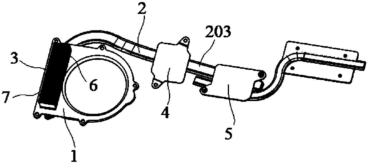
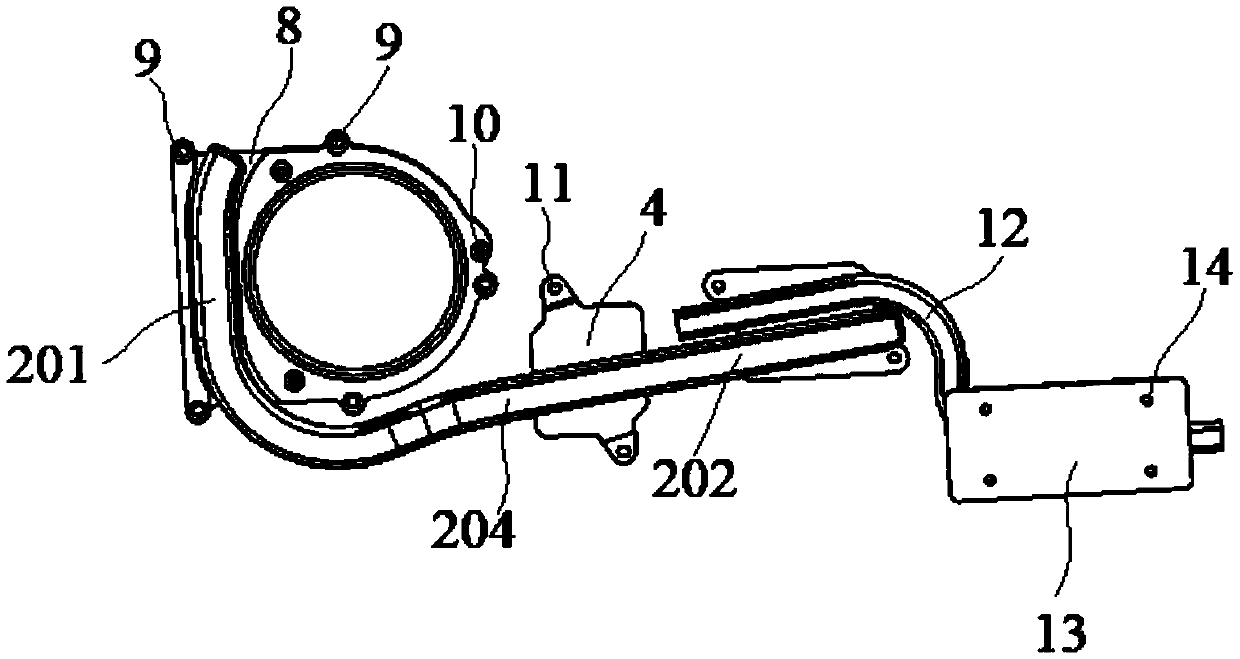
[0025] Embodiment 1: A military radiator with auxiliary heat dissipation function, including a mounting seat 1 for installing a fan, a main heat pipe 2, a heat dissipation fin group 3, a first heat absorbing fin 4 and a second heat absorbing fin 5, so The heat dissipation fin group 3 is arranged on one side surface of the installation base 1, and the other side surface of the installation base 1 is connected to the heat dissipation end 201 of the main heat pipe 2. The first heat absorption fin 4 and the second heat absorption fin 5 They are respectively connected to the heat-absorbing end 202 of the main heat pipe 2, and the second heat-absorbing sheet 5 is located on the side of the first heat-absorbing sheet 4 opposite to the mounting seat 1;

[0026] The heat dissipation fin group 3 is formed by sequentially buckling fins arranged in parallel, thereby forming several air ducts arranged in parallel. One side of the air duct is the air inlet 6, and the other side is the air ou...

Embodiment 2

[0030] Embodiment 2: A military radiator with auxiliary heat dissipation function, including a mounting base 1 for installing a fan, a main heat pipe 2, a heat dissipation fin group 3, a first heat absorbing fin 4 and a second heat absorbing fin 5, the The heat dissipation fin group 3 is arranged on one side surface of the installation base 1, and the other side surface of the installation base 1 is connected to the heat dissipation end 201 of the main heat pipe 2. The first heat absorption fin 4 and the second heat absorption fin 5 They are respectively connected to the heat-absorbing end 202 of the main heat pipe 2, and the second heat-absorbing sheet 5 is located on the side of the first heat-absorbing sheet 4 opposite to the mounting seat 1;

[0031] The heat dissipation fin group 3 is formed by sequentially buckling fins arranged in parallel, thereby forming several air ducts arranged in parallel. One side of the air duct is the air inlet 6, and the other side is the air o...


PUM


Abstract

The invention discloses a military heat dissipation device with an auxiliary heat dissipation function. The heat dissipation device includes a mounting seat used for mounting a fan, a main heat guiding pipe, a heat dissipation fin group, a first heat absorption piece and a second heat absorption piece. The heat dissipation fin group is disposed on one side surface of the mounting seat. The secondheat absorption piece is located on a side of the first heat absorption piece opposite the mounting seat. The heat dissipation fin group is formed by sequentially fastening a plurality of fins arranged in parallel. A side which is of the mounting seat and is connected with the main heat guiding pipe is opened with a groove. A heat dissipation end of the main heat guiding pipe is embedded in the groove, and is in welded connection with the mounting seat. The mounting seat is opened with a plurality of lock holes. Another end of an auxiliary heat guiding pipe is equipped with a heat absorption piece. The heat absorption piece is opened with a plurality of lock connection holes. According to the heat dissipation device, deviation and crushing of heat guiding pipe positions are prevented, stability of an entire heat dissipation structure can be improved, thus all components in the heat dissipation system are enabled to be mutually complemented, and heat dissipation performance and heat dissipation stability of the heat dissipation device are improved.

Description

technical field [0001] The invention relates to a military radiator with auxiliary heat dissipation function, which belongs to the field of heat dissipation parts. Background technique [0002] With the development of electronic industry technology, the transistor density of various chips is increasing day by day. Although the speed of data processing is getting faster and faster, the power consumption and heat generation are also increasing. In order for the central processing unit to operate stably, a high-efficiency radiator has become an inevitable requirement. In order to maintain high-efficiency heat dissipation, the volume and weight of the radiator have to be larger and heavier. However, in the design of notebook computers, limited space has always been the biggest problem in design. Among the existing technologies, the most common and effective method is to use a fan to drive the air to exchange heat with the heat-collecting fins to take away the heat from the fins...

Claims


Application Information

Patent Timeline
Patent Type & Authority Applications(China)
IPC IPC(8): G06F1/20
CPCG06F1/203
Inventor 徐海
Owner 昆山品岱电子有限公司
Why Eureka
Try Eureka