Circuit board nut reinforcement device

A reinforcement device and circuit board technology, applied to nuts, printed circuits, printed circuits, etc., can solve problems such as unusable, circuit board sliding, etc., to achieve the effect of increasing firmness, increasing reliability, and ensuring accuracy

Active Publication Date: 2018-10-19
ZHENGZHOU YUNHAI INFORMATION TECH CO LTD
View PDF4 Cites 0 Cited by
  • Summary
  • Abstract
  • Description
  • Claims
  • Application Information

AI Technical Summary

Problems solved by technology

[0004] The present invention aims at the above-mentioned deficiencies existing in the prior art, and provides a circuit board nut reinforcement device. A positioning column is added at the lower end of the nut, and a positioning hole is opened on the circuit board. Through the cooperation of the positioning column and the positioning hole, the nut can be The position is fixed, and the nut will not shift during the welding process, ensuring the accuracy of the welding position of the nut, which solves the problem of sliding with the circuit board when there is no nut welding, which makes it unusable, avoids re-welding, and improves Welding quality, while saving maintenance costs and manpower, reducing costs

Method used


Image

  • Circuit board nut reinforcement device
  • Circuit board nut reinforcement device
  • Circuit board nut reinforcement device

Examples


Embodiment 1

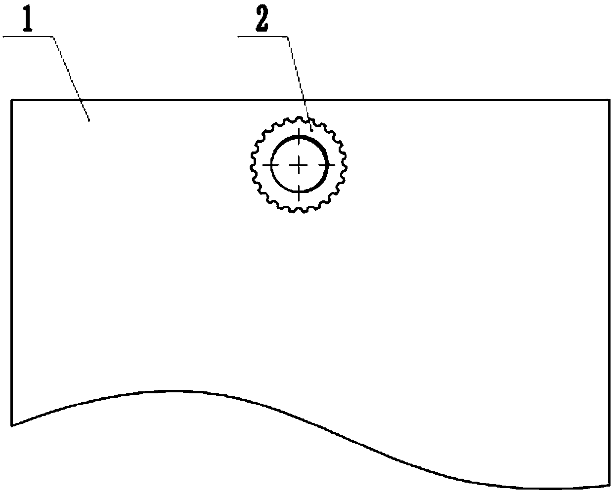
[0032] Such as figure 1 As shown, a circuit board nut reinforcement device includes a circuit board 1 and a nut 2, the nut 2 is connected to the circuit board 1, the lower end of the nut 2 is provided with a positioning post 3, and the circuit wrench 1 is provided with a positioning hole 101, the positioning post 3 is matched with the positioning hole 101, and the lower end surface of the nut 2 is connected with the circuit board 1 by soldering. In order to prevent the positioning post 3 from rotating in the positioning hole 101, resulting in weak welding, the positioning post 3 is designed It is a prism structure, and the shape of the positioning hole 101 matches the positioning column 3 .

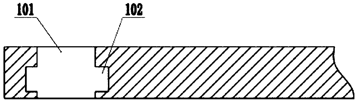
[0033] In order to avoid long-term use, the welding place becomes loose, and the positioning column 3 falls off from the positioning hole 101, such as figure 2 As shown, the inner wall of the positioning hole 101 is provided with an anti-off groove 102, and the number of the anti-off gr...

Embodiment 2

[0037] This embodiment is compared with the first embodiment, the difference lies in the difference between the anti-off block 4 and the anti-off hole 301 .

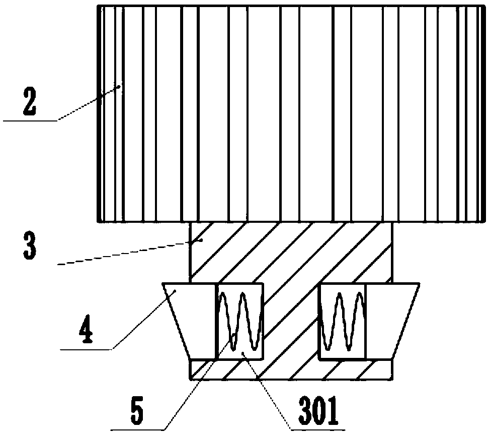
[0038] Such as Figure 5 As shown, the anti-off hole 301 is a through hole, the number of anti-off grooves 102 is two, the two ends of the anti-off hole 301 are provided with inner flanges 302, and the number of the anti-off blocks 4 is two. One, two springs 8 are arranged between the two anti-off blocks 4, such as Figure 6 As shown, the anti-off block 4 includes a slide block 6 and an insert block 7, the slide block 6 cooperates with the inner wall of the anti-off hole 301, the side wall of the insert block 7 cooperates with the inner flange 302, and one end of the slide block 6 matches with the inner wall of the anti-off hole 301 The plug 7 is connected, the other end of the slider 6 is provided with a spring groove 601, and the end of the spring 2 8 is arranged in the spring groove 601 and connected with the bottom ...


PUM


Abstract

The invention discloses a circuit board nut reinforcement device. The device comprises a circuit board and a nut. The nut is connected to the circuit board. The lower end of the nut is provided with apositioning column. The circuit board is provided with a positioning hole. The positioning column is cooperated with the positioning hole. The lower end surface of the nut is connected to the circuitboard through tin soldering. The lower end of the nut is additionally installed with the positioning column. The positioning hole is arranged on the circuit board. Through the cooperation of the positioning column and the positioning hole, the nut can be fixed. During a welding process, the nut does not generate offset so that the accuracy of a nut welding position is guaranteed. A current problem that the nut glides with the circuit board so that the nut can not be used during nut welding is solved. Rewelding is avoided, welding quality is increased, simultaneously, maintenance cost and manpower are saved and cost is reduced.

Description

technical field [0001] The invention relates to the technical field of circuit boards, in particular to a circuit board nut reinforcing device. Background technique [0002] At present, the application of nuts on circuit boards is very common. During assembly, the screws and nuts are used to fix the parts. The positioning of the nuts on the circuit board is very important. If the nuts are not positioned correctly, it will cause The part corresponding to the nut cannot be fixed accurately. [0003] At present, the nut on the circuit board has the problem of welding offset. During the welding process, due to the melting solder paste, the friction between the nut and the circuit board is small, and the nut will slide slightly during welding. The position deviation of the nut will cause It is impossible to cooperate with the connecting piece, and it is a waste of cost and manpower to re-weld the nut. Contents of the invention [0004] The present invention aims at the above-...

Claims


Application Information

Patent Timeline
Patent Type & Authority Applications(China)
IPC IPC(8): H05K1/02F16B39/38
CPCF16B39/38H05K1/02H05K2201/10333
Inventor 张小行
Owner ZHENGZHOU YUNHAI INFORMATION TECH CO LTD
Why Eureka
Try Eureka