Gas exhausting device for injection mold

An exhaust device and injection mold technology, applied in the field of injection mold exhaust device, can solve problems such as inability to close, discharge of molding materials, and unsmooth return of falling chips, and achieve the effect of improving durability and life, and preventing leakage.

Inactive Publication Date: 2018-10-23
金天燮
View PDF3 Cites 1 Cited by
  • Summary
  • Abstract
  • Description
  • Claims
  • Application Information

AI Technical Summary

Problems solved by technology

[0010] However, since two elastic members are connected in series, the modulus of elasticity increases, and it cannot be closed even by injection pressure, causing the problem that the molding material is discharged to the second discharge hole.
However, if the elastic coefficients of both the first elastic member and the second elastic member are lowered, the return of the dropped chip will not be smooth.

Method used


Image

  • Gas exhausting device for injection mold
  • Gas exhausting device for injection mold
  • Gas exhausting device for injection mold

Examples


Embodiment Construction

[0046] Hereinafter, an embodiment according to the present invention will be described in more detail with reference to the accompanying drawings.

[0047] The description with reference to the drawings is for easier understanding of the present invention, and the scope of the present invention is not limited thereto. Also, when describing the present invention, detailed descriptions related to known technologies will be omitted if they may obscure the gist of the present invention.

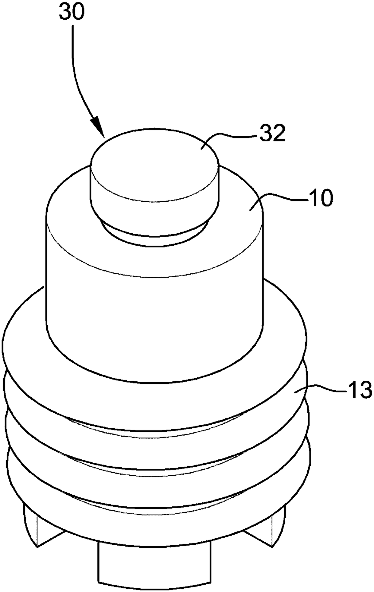
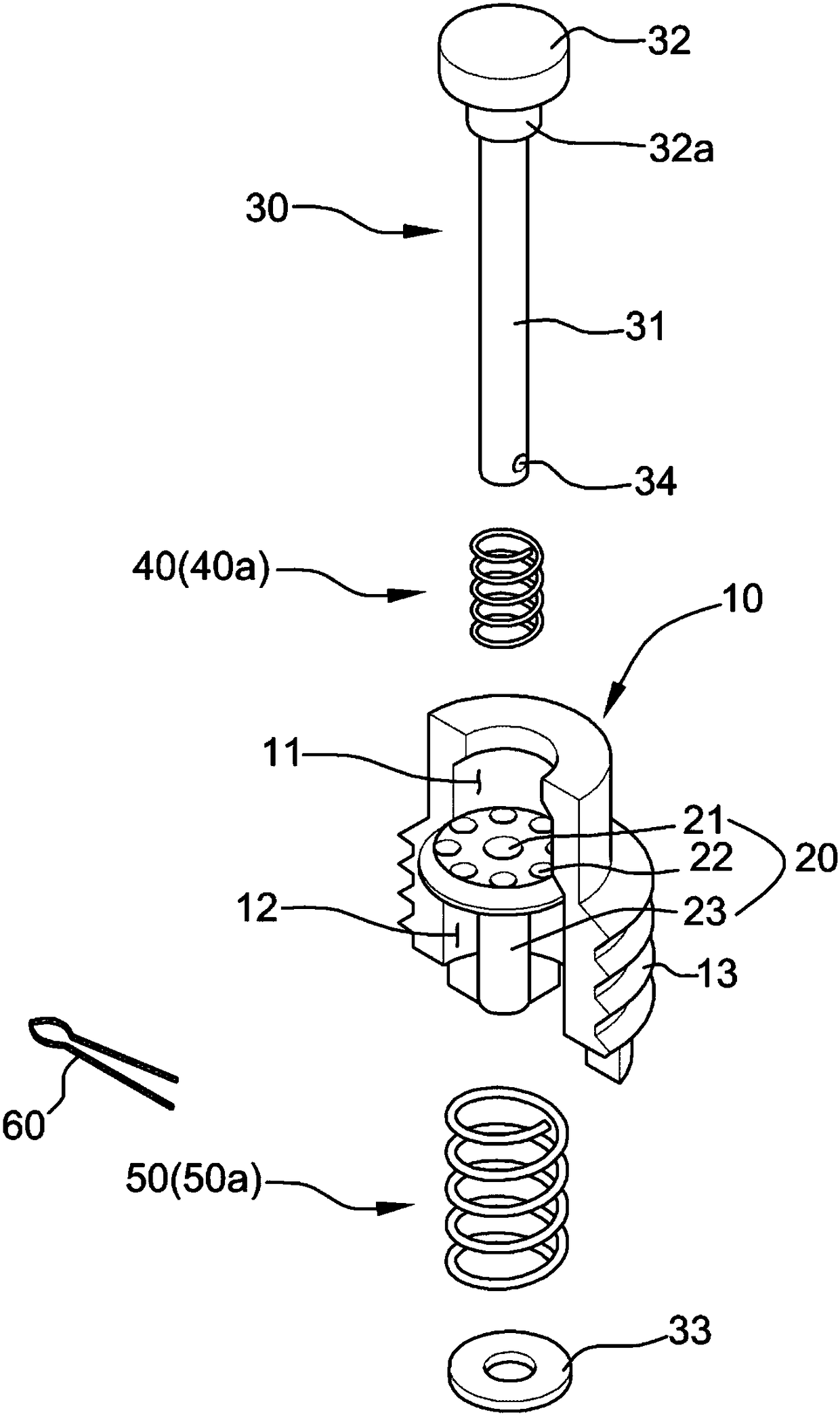
[0048] figure 1 is a perspective view of an injection mold exhaust device according to an embodiment of the present invention; figure 2 for in figure 1 The exploded perspective view of the present invention illustrated in; image 3 for in figure 1 A cross-sectional view of the invention illustrated in .

[0049] As shown in the figure, the injection mold exhaust device according to the present invention is to discharge the air or gas remaining in the cavity of the injection mold, and genera...


PUM


Abstract

Provided is a gas exhausting device for an injection mold. The gas exhausting device includes: an inflow groove, an inflow seat, a poppet valve, a first elastic part and a second elastic part. The inflow groove, tubular in shape is arranged on an inner surface of a discharge channel in a communicating manner such that a cavity communicates with the outside. As a result, gas remaining in the cavityflows in and out. The inflow seat is transversely arranged in the interior of the inflow groove and divided into a first gas inflow channel and a second gas inflow channel. The center of the inflow seat is equipped with a central hole enabling the poppet valve to communicate. Multiple gas communicating channels are formed along the outside of the central hole. The poppet valve comprises a main body communicating with the central hole, a head part formed at one end of the main body and used for closing the first gas inflow channel through reciprocating motion and a support ring formed at the other end of the main body. The first elastic part is installed between the head of the poppet valve and the inflow seat and elastically supports one end of the poppet valve. The second elastic part isinstalled between the support ring of the poppet valve and the inflow seat and elastically supports the other end of the poppet valve.

Description

technical field [0001] The invention relates to an exhaust device for an injection mold, in particular to an exhaust device for an injection mold that can smoothly suck and discharge the gas remaining in the cavity of the injection mold during the injection molding process. Background technique [0002] Generally, when an injection-molded article is produced using a mold, molten resin is poured into a cavity (cavity, cavity) formed by connecting an upper mold and a lower mold. At this time, as the molten resin, soluble resins such as plastics are generally used. [0003] However, when the molten resin is quickly injected into the cavity, the air contained in the cavity cannot be discharged, and the molten resin mixed with the air remaining in the cavity is directly cooled and made into an injection molding, resulting in Various defects including air bubbles and pores (porosity) are formed. [0004] In particular, when manufacturing outsoles, midsoles, and insoles of shoes ...

Claims


Application Information

Patent Timeline
IPC IPC(8): B29C45/34
CPCB29C45/34B29C45/63
Inventor 金天燮
Owner 金天燮
Why Eureka
Try Eureka