Energy saving oil pumping unit

A technology of pumping units and electric motors, which is applied in the field of pumping units, can solve the problems of high power consumption, poor balance effect, and large start-up impact, etc., and achieve the effects of avoiding complex structures, reducing loads, and ensuring balance

Active Publication Date: 2018-10-23
东营市东达机械制造有限责任公司
View PDF6 Cites 0 Cited by
  • Summary
  • Abstract
  • Description
  • Claims
  • Application Information

AI Technical Summary

Problems solved by technology

[0002] The oil pumping unit is a kind of machinery and equipment for oil extraction. Most of the oil fields in my country are low-permeability, low-energy and low-yield oil fields. Upgrading from the formation, changing oil with water or electricity is the reality of my country's oil fields. Therefore, electricity costs account for a considerable proportion of my country's oil production costs. Long-term low-cost advantages, energy saving and consumption reduction have become an unavoidable proposition for oilfields to stabilize and increase production. The pumping units currently used are mainly beam pumping units. Although this type of pumping unit has a simple Reliable and other advantages, but it still has the disadvantages of bulky size, large start-up impact, high power consumption, poor balance effect, etc., can not meet the needs of energy saving, and has poor practicability

Method used


Image

  • Energy saving oil pumping unit
  • Energy saving oil pumping unit
  • Energy saving oil pumping unit

Examples


Embodiment Construction

[0023] The following will clearly and completely describe the technical solutions in the embodiments of the present invention with reference to the accompanying drawings in the embodiments of the present invention. Obviously, the described embodiments are only some, not all, embodiments of the present invention. Based on the embodiments of the present invention, all other embodiments obtained by persons of ordinary skill in the art without making creative efforts belong to the protection scope of the present invention.

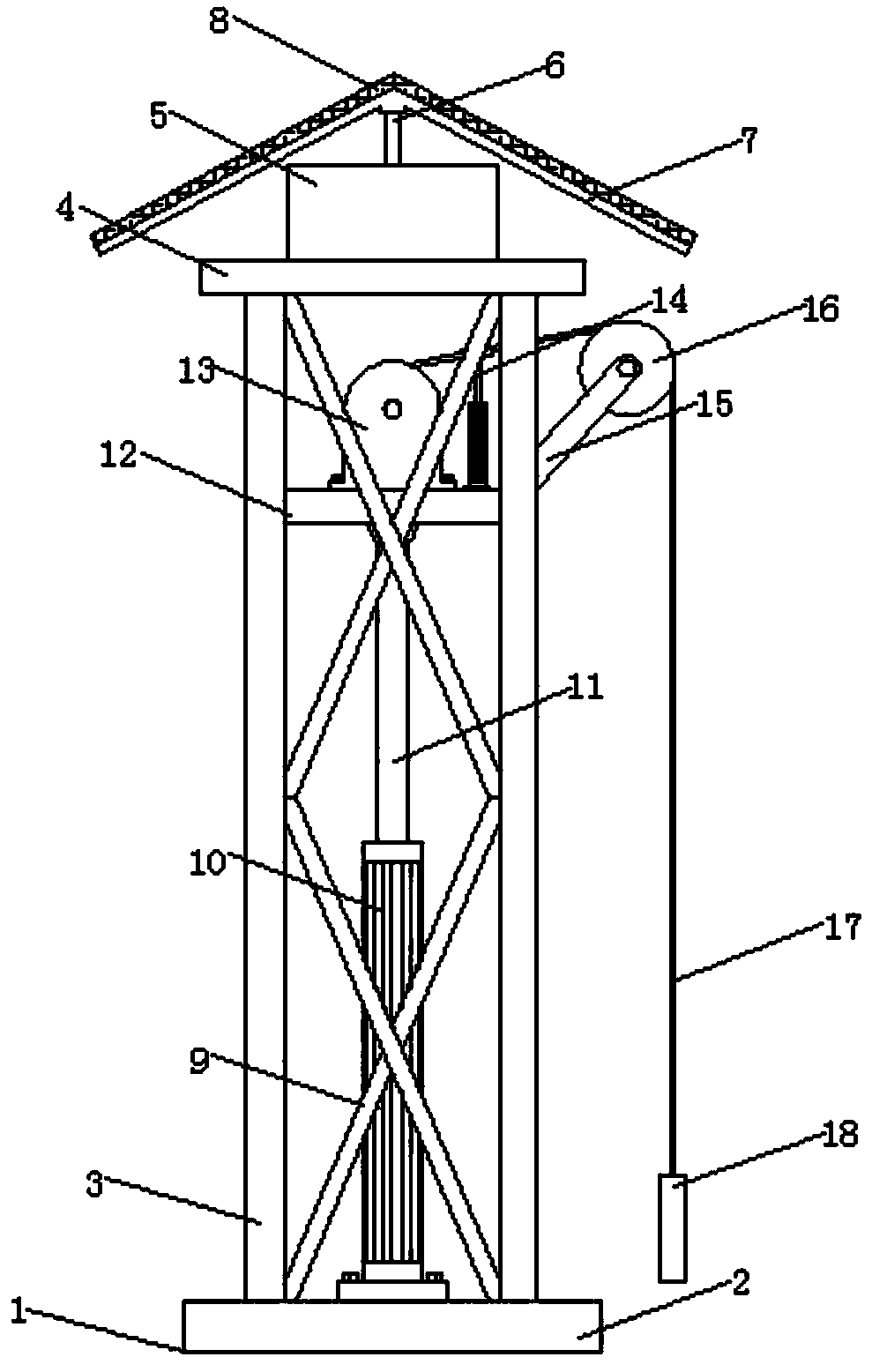
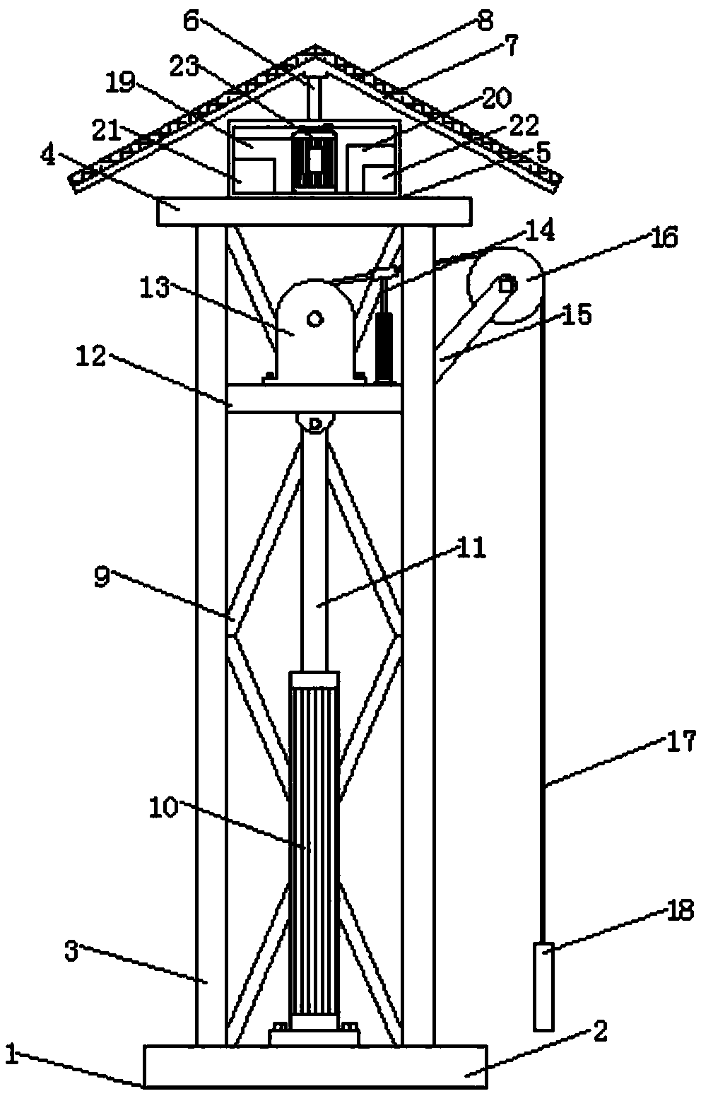
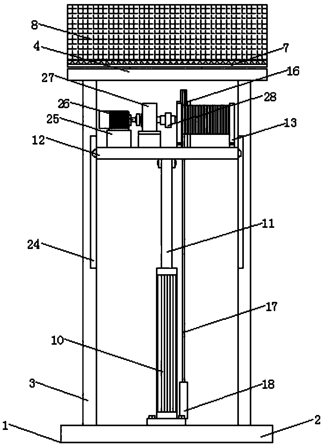
[0024] see Figure 1-6, the present invention provides a technical solution: an energy-saving pumping unit, including a pumping unit body 1, a base 2, a bracket 3, a top plate 4, a control box 5, a rotating shaft 6, a mounting plate 7, a solar panel 8, a reinforced Rod 9, hydraulic cylinder 10, telescopic rod 11, slide plate 12, reel 13, jacking device 14, support plate 15, guide wheel 16, steel wire rope 17, sucker rod 18, battery 19, inverter 20, programmabl...


PUM


Abstract

The invention discloses an energy saving oil pumping unit, wherein the bottom of the oil pumping unit body is provided with a base; a support is installed on a top of the base; a chute is opened on atop end of the inner side of the support; a slide plate is installed inside the chute; a second Y355 electric motor is installed on one end of the top of the slide plate; a transmission shaft is fixedly connected to one end of the second Y355 electric motor; a speed reducer is installed at one end of the transmission shaft; a connecting shaft is fixedly connected to one end of the speed reducer; areel is installed at one end of the connecting shaft; a wire rope is arranged around the outer side of the reel; a sucker rod is installed at the bottom end of the wire rope, and a hydraulic cylinderis installed at the bottom of the slide plate; the top of the hydraulic cylinder is provided with a telescopic rod, and a top plate is mounted on the top of the support. The hydraulic cylinder of thepresent invention is hinged to the slide plate by a telescopic rod. The hydraulic cylinder can move the slide plate up and down through the telescopic rod, thereby realizing the change of the strokeof the pumping unit body. The operation is simple and quick, and it is convenient to freely adjust according to the needs, which expands the applicable range of the pumping unit body and improves itspracticability.

Description

technical field [0001] The invention relates to the technical field of an oil pumping unit, in particular to an energy-saving oil pumping unit. Background technique [0002] The oil pumping unit is a kind of machinery and equipment for oil extraction. Most of the oil fields in my country are low-permeability, low-energy and low-yield oil fields. Upgrading from the formation, changing oil with water or electricity is the reality of my country's oil fields. Therefore, electricity costs account for a considerable proportion of my country's oil production costs. Long-term low-cost advantages, energy saving and consumption reduction have become an unavoidable proposition for oilfields to stabilize and increase production. The pumping units currently used are mainly beam pumping units. Although this type of pumping unit has a simple Reliable and other advantages, but it still has the disadvantages of bulky size, large start-up impact, high power consumption, poor balance effect, etc...

Claims


Application Information

Patent Timeline
Patent Type & Authority Applications(China)
IPC IPC(8): E21B43/00H02J7/35G05B19/05
CPCE21B43/126G05B19/05H02J7/35
Inventor 王根琴
Owner 东营市东达机械制造有限责任公司
Why Eureka
Try Eureka