
Flat-convex engaged pure rolling bevel gear mechanism for transmission of crossed shafts

A cross-axis, pure rolling technology, applied in the direction of transmission, gear transmission, belt/chain/gear, etc., can solve the uncertain value of the coincidence degree of the transmission pair, the strict design of the coincidence degree cannot be realized, and it is not conducive to the uniform load distribution And other issues

Inactive Publication Date: 2018-10-23
CHINA UNIV OF GEOSCIENCES (WUHAN)
View PDF7 Cites 2 Cited by
  • Summary
  • Abstract
  • Description
  • Claims
  • Application Information

AI Technical Summary

Problems solved by technology

The limitations of the above two transmission mechanisms are that their design methods are based on the theory of space curve meshing, and the meshing tooth surface depends on the calculation and solution of the curve meshing equation. The meshing method is a concave-convex meshing form, and the meshing point is located on the edge of the concave tooth profile. Due to edge contact during transmission, excessive local stress will be generated, which will easily cause the tooth top of the concave tooth to break and cause transmission failure. It cannot be used for conventional power and high-speed heavy-duty transmission in industrial production.
In addition, the design methods of the above two mechanisms cannot realize the strict design of the coincidence degree, which makes the value of the coincidence degree of the transmission pair uncertain, which is not conducive to the uniform distribution of loads.
Moreover, they can only realize the motion and power transmission between two parallel axes in the plane, but cannot realize the motion and power transmission between two orthogonal axes in the plane.
Therefore, their scope of use is greatly limited
Chinese patent document, application number 201310049845.5, discloses "bevel gear meshing pair based on conjugate curves", including bevel gear I and bevel gear II with mutual point meshing and tooth profile curves of circular arc, the bevel gear mechanism has transmission High efficiency; the tooth surface is easy to process and manufacture, the transmission error is small, and the service life is long; but the bevel gear also has the tooth surface moving along the conjugate curve when the bevel gear I and the bevel gear II mesh, so there is relative sliding between the tooth surfaces , the tooth surface has failure modes such as gluing, wear and plastic deformation

Method used


Image

  • Flat-convex engaged pure rolling bevel gear mechanism for transmission of crossed shafts
  • Flat-convex engaged pure rolling bevel gear mechanism for transmission of crossed shafts
  • Flat-convex engaged pure rolling bevel gear mechanism for transmission of crossed shafts

Examples


Embodiment 1

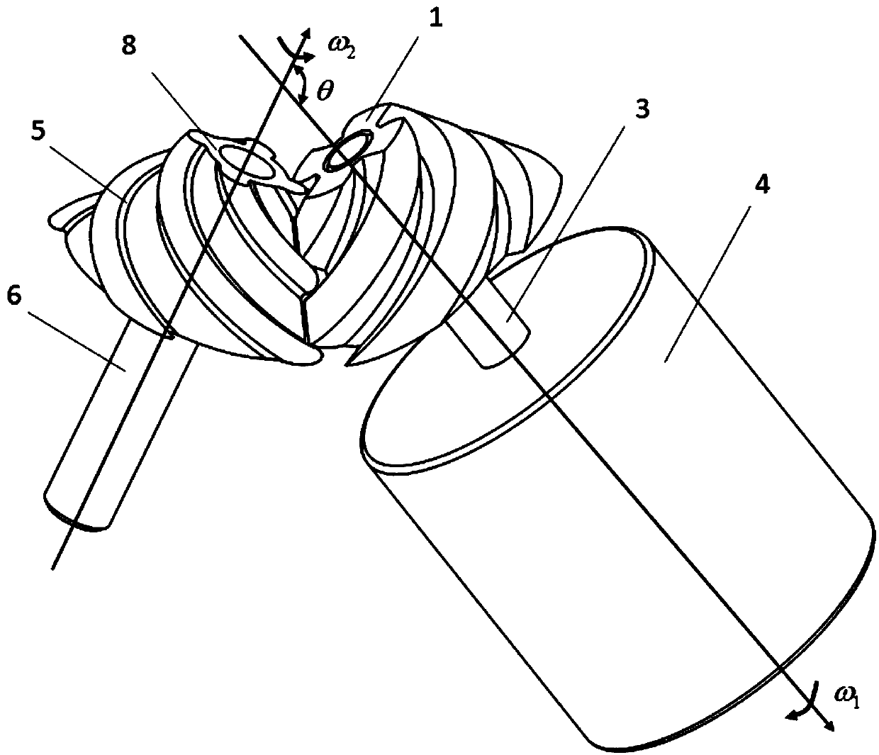
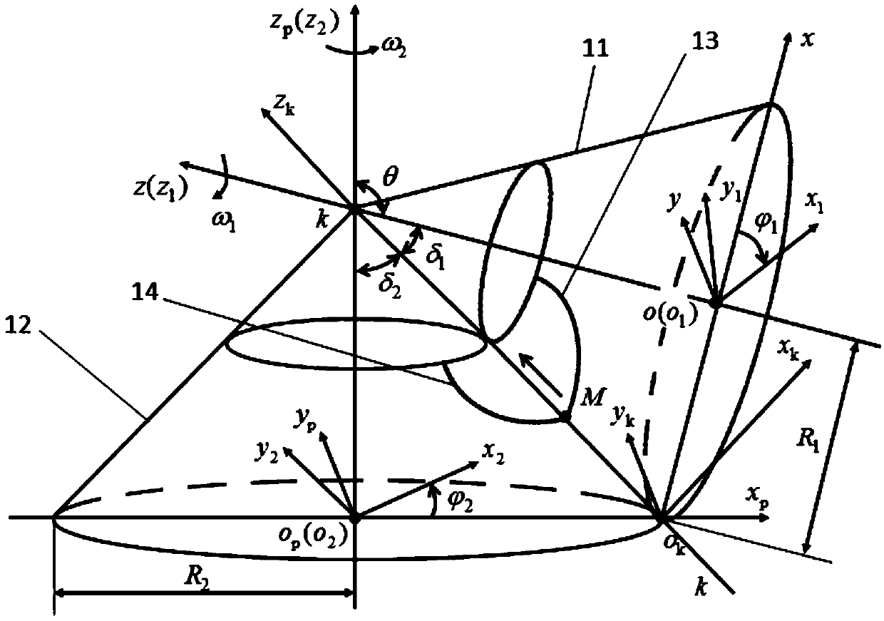
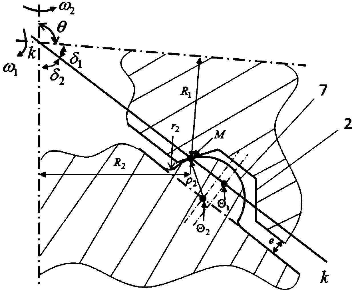
[0114] The present invention provides a flat-convex meshing pure rolling bevel gear mechanism for cross shaft transmission, which is applied to the transmission with a transmission ratio of 1 between two cross shafts in the plane, such as figure 1 As shown, it includes a small wheel 1 and a large wheel 8, the small wheel 1 and the large wheel 8 form a pair of transmission pairs, the small wheel 1 is connected to the input shaft 3 through the small wheel center hole 15, and the large wheel 8 is connected to the The wheel center hole 16 is connected to the output shaft 6, that is, the large wheel 8 is connected with the driven load through the output shaft 6; the axes of the small wheel 1 and the large wheel 8 intersect, and the The included angle between the angular velocity vectors is θ, and θ=2π / 3 radians (rad) in this example. figure 2 It is a schematic diagram of the spatial coordinate system of the plano-convex meshing pure rolling bevel gear mechanism used in the cross s...

Embodiment 2

[0211] Apply the flat-convex meshing pure rolling bevel gear mechanism of the present invention for cross shaft transmission to the speed-up transmission between two vertical cross shafts, at this time θ=π / 2 radians (rad). Such as Figure 10 As shown, the large wheel 8 is used to connect the input shaft 3 through the center hole 16 of the large wheel, and the small wheel 1 is connected to the output shaft 6 through the center hole 15 of the small wheel, that is, the small wheel 1 is connected to the driven load through the output shaft 6; the small wheel 1 The axes of the bull wheel 8 are perpendicular to each other, and their angular velocity angle at this moment is θ=π / 2 radians (rad). In this embodiment, there are eight spiral arc teeth 7 on the bull wheel 8, and four spiral trapezoidal grooves 2 on the small wheel 1. When the input shaft 3 drives the bull wheel 8 to rotate, the design coincidence degree ε=2. Because when the big wheel 8 and the small wheel 1 are installed...


PUM


Abstract

The invention provides a flat-convex engaged pure rolling bevel gear mechanism for transmission of crossed shafts and a design method thereof. The flat-convex engaged pure rolling bevel gear mechanismfor transmission of the crossed shafts comprises a small wheel and a large wheel which form a pair of transmission pairs, wherein the axes of the small wheel and the large wheel are crossed; spiral trapezoidal slots are uniformly formed in the outer surface of the cone of the small wheel; spiral arc-shaped teeth are uniformly distributed on the outer surface of the cone of the large wheel; the structures of the spiral arc-shaped teeth and the spiral trapezoidal slots are jointly determined by a pure rolling engaging line parameter equation and a transmission ratio and the like, and the spiralarc-shaped teeth are matched with the spiral trapezoidal slots; when the large wheel and the small wheel are mounted, the spiral arc-shaped teeth and the spiral trapezoidal slots are engaged, and thesmall wheel and the large wheel are driven by a driver to rotate, so that transmission between two crossed shafts is achieved. The flat-convex engaged pure rolling bevel gear mechanism for transmission of crossed shafts provided by the invention can be used for a design of a pure rolling bevel gear mechanism for the crossed shafts, has the characteristics of being simple in design, easy to process, high in transmission efficiency, great in coincidence degree, high in bearing capacity and the like, and can be widely applied to the fields of small, micro and conventional machinery which is difficult to lubricate.

Description

technical field [0001] The invention relates to the technical field of gear transmission, in particular to a flat-convex meshing pure rolling bevel gear mechanism for cross shaft transmission. Background technique [0002] As the core basic components of machinery, gears are widely used in machine tools, automobiles, robots, wind power, coal mines, aerospace and other equipment manufacturing fields and the main battlefield of the national economy. Their performance directly determines the quality of major equipment and high-end industrial products. performance and reliability. Research on core basic components such as high-performance gears is a key factor in promoting industrial transformation and upgrading, enhancing the core competitiveness of national industries, and an important measure to realize the "Made in China 2025" strategy of strengthening the country. [0003] At present, the main problem facing my country's gear industry is the obvious lack of design and manu...

Claims


Application Information

Patent Timeline
Patent Type & Authority Applications(China)
IPC IPC(8): F16H1/14F16H55/17F16H55/08G06F17/50
CPCF16H1/14F16H55/08F16H55/17F16H2055/0866G06F30/17G06F30/367
Inventor 陈祯文国军曾鸣杨静
Owner CHINA UNIV OF GEOSCIENCES (WUHAN)
Learn More