
Seal Member and electrical connector

A technology for sealing members and electrical connectors, which is applied in the direction of vehicle connectors, connections, and parts of connecting devices, etc., to achieve the effects of suppressing manufacturing costs, reducing the number of parts, and suppressing size

Inactive Publication Date: 2018-10-23
TYCO ELECTRONICS JAPAN GK
View PDF1 Cites 0 Cited by
  • Summary
  • Abstract
  • Description
  • Claims
  • Application Information

AI Technical Summary

Problems solved by technology

The housing surrounds the sealing cover and the plug housing

Method used


Image

  • Seal Member and electrical connector
  • Seal Member and electrical connector
  • Seal Member and electrical connector

Examples


Embodiment Construction

[0029] Hereinafter, embodiments of the present invention will be described with reference to the drawings.

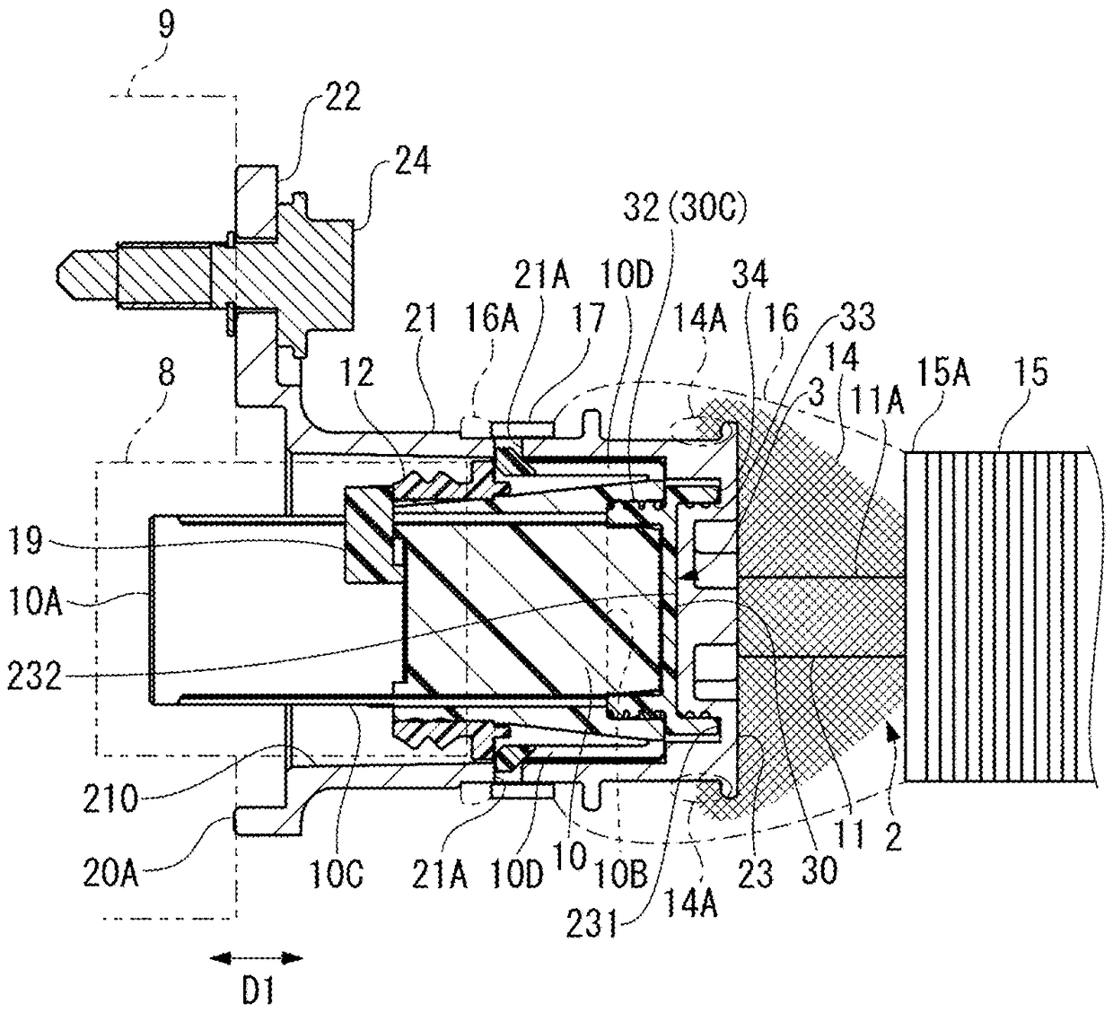
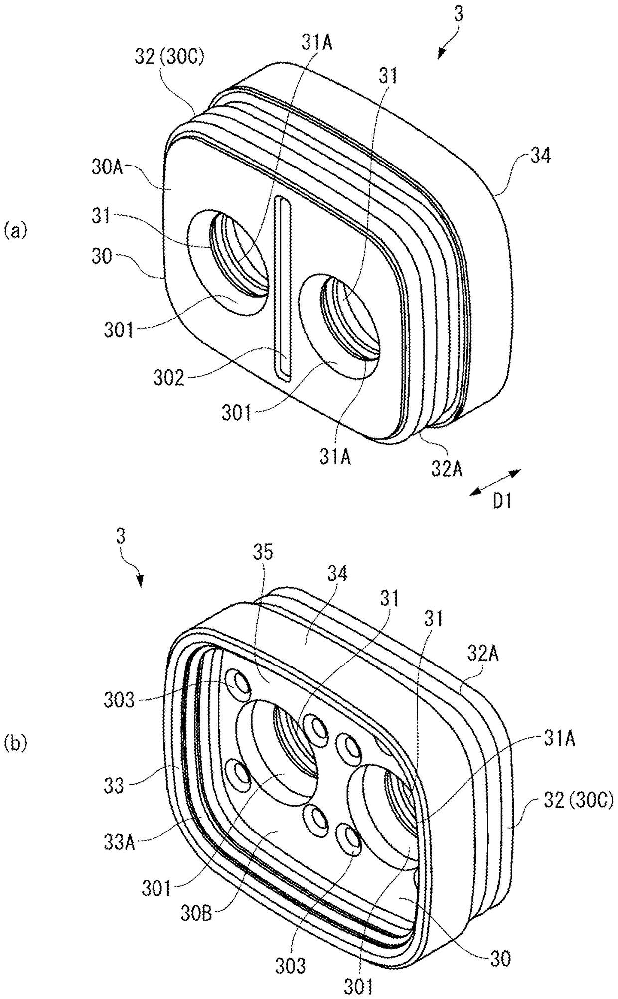
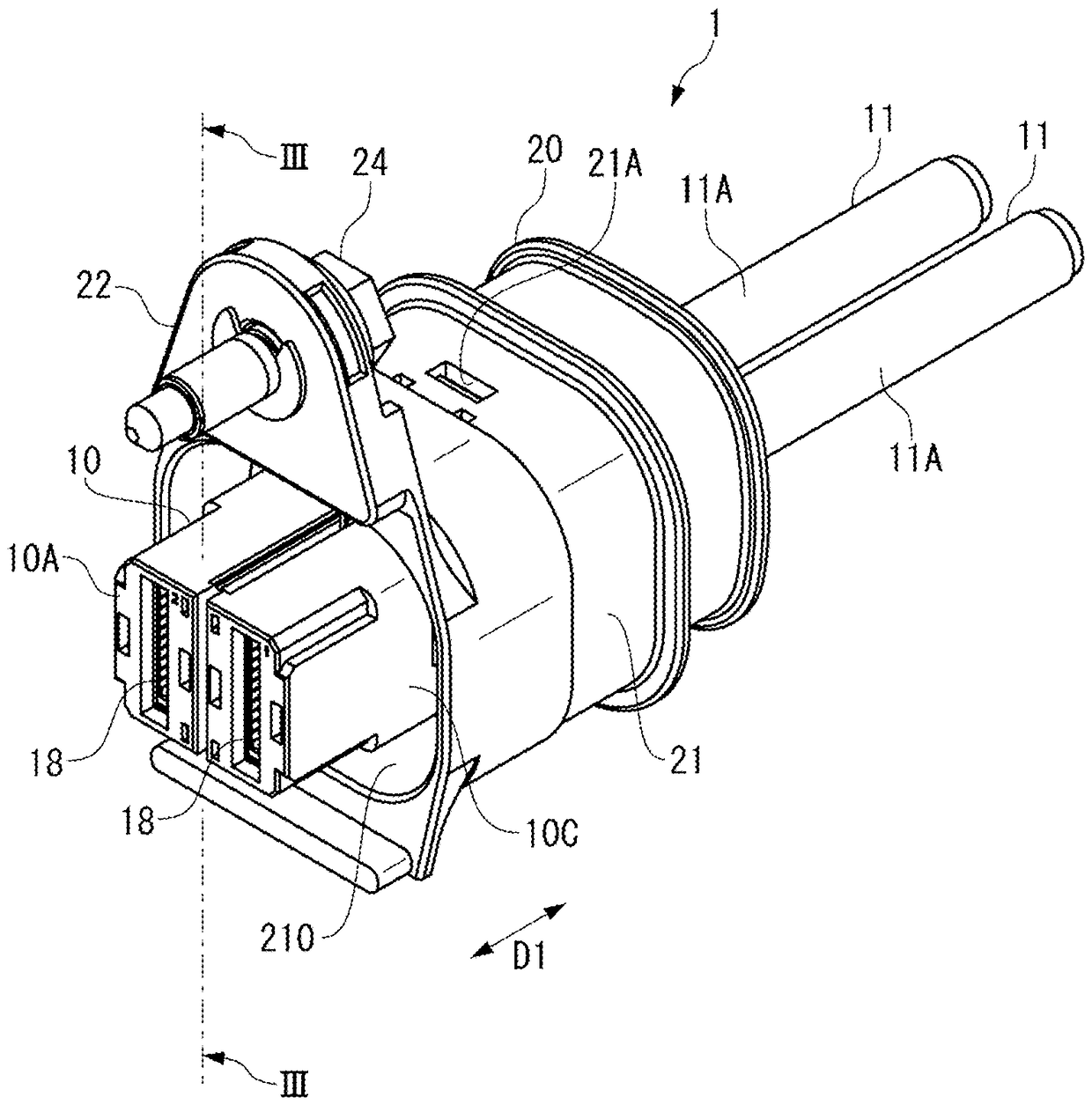
[0030] figure 1 and figure 2 The shown electrical connector 1 (plug connector) includes: a housing 10 from which two electric wires 11 are drawn; a shell 20 for electromagnetic shielding; a sealing member 3 ( image 3 and Figure 4 ); and the fitting part seal 12 ( image 3 ).

[0031] In this specification, the side where the electric wire 11 is drawn out of the electrical connector 1 is defined as "rear", and the opposite side, that is, the side that is mated with the mating connector (cover connector) along the mating direction D1 is defined as "front". . With respect to mating connectors, typically part of the device housing ( image 3 The metal components 9) are assembled.

[0032] The electrical connector 1 and the mating connector are suitable for electrical connection of high-voltage equipment such as a PCU (Power Control Unit) mounted on a vehicle. In ...


PUM


Abstract

Size reduction is achieved while the performance of preventing entry of water required for an electrical connector achieving an electromagnetic shielding effect is maintained. A seal member (3) used for an electrical connector (1) is configured to be penetrated by an electric-wire (11) extending rearwardly from a housing (10) enclosed with a shell (20) made of metal. The seal member (3) is pressedbetween the housing (10) and a shell bottom portion (23). The seal member (3) is integrally provided with an electric-wire seal portion (31) configured to come into contact with an outer peripheral portion of the electric-wire (11), a housing seal portion (32) located on an outer end portion (30C) of a radial outside of a base portion (30) formed with the electric-wire seal portion (31), and configured to be pressed against the housing (10), and a shell seal portion (33) configured to be pressed against at least the shell bottom portion (23) of the shell (20).

Description

technical field [0001] The present invention relates to a sealing member for achieving waterproofing of an electrical connector provided with a metal housing. Background technique [0002] A waterproof connector is known that is provided with a wire seal (bundle of rubber plugs) disposed at the rear end of a housing of a plug connector and tightly fitted around a plurality of wires (Patent Document 1). The wire seal of Patent Document 1 is formed integrally with a housing of a cap connector (cap connector) and a housing sealing portion that is tightly fitted from the inside. [0003] In a shield connector (shield connector) provided with a metal case surrounding the plug housing, the wire seal arranged at the rear end portion of the plug housing is pressed by the sealing cover. Furthermore, a sealing member different from the wire seal is arranged between the housing and the plug housing or the cover housing. [0004] prior art literature [0005] patent documents [000...

Claims


Application Information

Patent Timeline
Patent Type & Authority Applications(China)
IPC IPC(8): H01R13/52
CPCH01R13/5202H01R13/5208H01R13/6593H01R13/6596H01R2201/26H01R13/621H01B5/12H01R13/518H01R13/514
Inventor 古屋澄美雨宫真二长岛史
Owner TYCO ELECTRONICS JAPAN GK
Learn More