High-frequency transformer laser peeling machine

A technology of high-frequency transformers and stripping machines, which is applied in the direction of cable installation devices, electrical components, and equipment for dismantling/armouring cables, etc., which can solve the problems of braiding layer or inner conductor damage, low efficiency of manual stripping, etc., and improve stripping efficiency Effect

Inactive Publication Date: 2018-10-23
重庆尚润电子有限公司
0 Cites 0 Cited by

AI-Extracted Technical Summary

Problems solved by technology

Some waste products will inevitably be produced during the production of coaxial cables. At present, the processing method of these waste products in the factory is mainly to manually peel off the outer layer or insulation layer from the braid or inner conductor,...

Method used

As the further improvement of above-mentioned technical scheme, described setting ring both sides are provided with support 11, described support is provided with fixed ring 12, described fixed ring inner side is provided with air bag layer 13, and air bag layer is the rubber that inflates automatically Airbag structure, the cable passes through the fixing ring. The cable passes through the fixing ring. On the one hand, the fixing ring guides the cable. On the other hand, the airbag layer holds the cable. Only when the cable is in a relatively tight state can there be a relative tension between the cable and the airbag layer. Sliding, therefore, avoids the loosening of the cable passing through the placement ring, further facilitating the laser cutting of its skin.
The present invention will be described in detail below in conjunction with accompanying drawing, as shown in Figure 1: the high-frequency transformer laser peeling machine of the present embodiment, comprises cable delivery r...

Abstract

The invention discloses a high-frequency transformer laser peeling machine, which comprises a cable conveying roller, a laser generator, a skin scraper and an arrangement ring driven to rotate througha driving structure, wherein the laser generator is arranged at the inner wall of the arrangement ring; and the cable passes through the arrangement ring. The laser peeling machine with the structurecan effectively improve the peeling efficiency.

Application Domain

Technology Topic

Image

  • High-frequency transformer laser peeling machine

Examples

  • Experimental program(1)

Example Embodiment

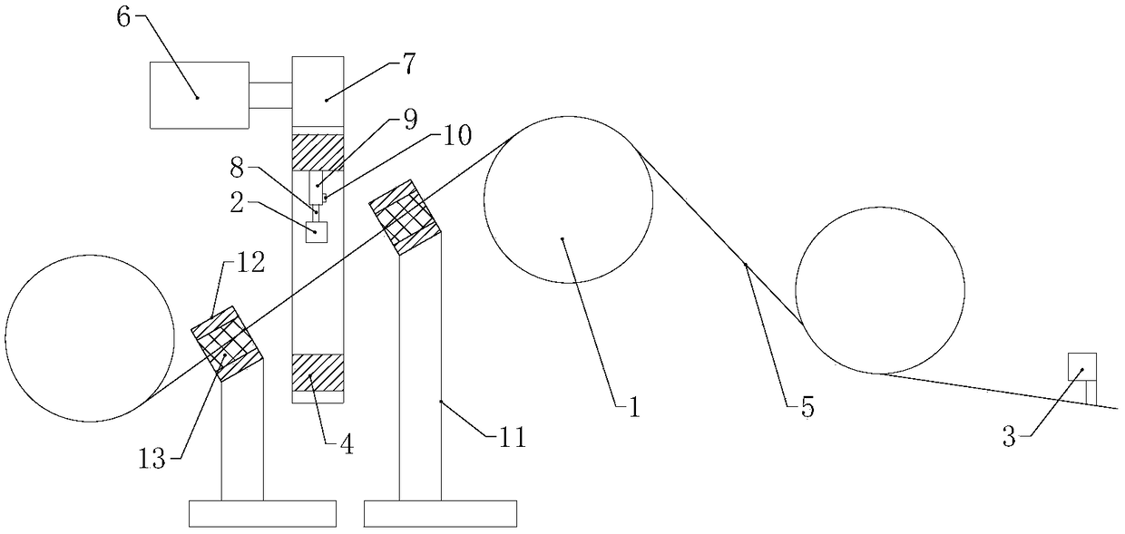
[0012] The present invention will be described in detail below with reference to the drawings, such as figure 1 Shown: the high-frequency transformer laser peeling machine of this embodiment includes a cable conveying roller 1, a laser generator 2 and a skin scraper 3, and also includes a mounting ring 4 driven to rotate by a driving structure, and the laser generator is set in the mounting position In the inner wall of the ring, the cable 5 passes through the mounting ring. The drive structure includes a motor 6 and a gear 7 fixedly sleeved on the output shaft of the motor. The outer wall of the mounting ring is provided with a ring gear. The gear meshes with the ring gear for transmission. Both the mounting ring and the placement ring are supported by corresponding supporting structures. This is the prior art and will not be described in detail. Using the laser peeling machine of this structure, the laser generator emits laser to cut the cable sheath. During the cutting process, the driving structure drives the placement ring to rotate around its axis, and then drives the laser generator to circle the cable, thereby realizing the cable sheath Full circle cutting effectively improves the peeling efficiency.
[0013] As a further improvement of the above technical solution, the laser generator is connected to the inner wall of the mounting ring through an adjusting rod. The adjusting rod includes a rod 8 and a cylinder 9 that are slidably sleeved, and a locking screw is used between the rod and the cylinder. 10 Achieve sliding locking, specifically, the locking screw passes through the side wall of the cylinder body and then comes into tight contact with the rod body, and the sliding locking of the two is realized by friction. The distance between the laser generator and the cable can be adjusted by adjusting the extension or shortening of the rod, so as to ensure that the laser intensity can smoothly cut the cable skin without damaging the conductor core of the cable.
[0014] As a further improvement of the above technical solution, the mounting ring is provided with brackets 11 on both sides, a fixing ring 12 is arranged on the bracket, and an airbag layer 13 is arranged on the inner side of the fixing ring. The airbag layer is a self-inflating rubber airbag structure. The cable passes through the fixing ring. The cable passes through the fixing ring. On the one hand, the fixing ring has a guiding effect on the cable. On the other hand, the airbag layer has a clamping effect on the cable. Only when the cable is in a relatively tight state can the cable and the airbag layer face each other. Sliding, therefore, avoids the loose state of the cable passing through the placement ring, which further facilitates the laser cutting of its skin.
[0015] Finally, it should be noted that the above embodiments are only used to illustrate the technical solutions of the present invention and not to limit them. Although the present invention has been described in detail with reference to the preferred embodiments, those of ordinary skill in the art should understand that the technical solutions of the present invention can be implemented Modifications or equivalent replacements without departing from the purpose and scope of the technical solution of the present invention should be covered by the scope of the claims of the present invention.

PUM

no PUM

Description & Claims & Application Information

We can also present the details of the Description, Claims and Application information to help users get a comprehensive understanding of the technical details of the patent, such as background art, summary of invention, brief description of drawings, description of embodiments, and other original content. On the other hand, users can also determine the specific scope of protection of the technology through the list of claims; as well as understand the changes in the life cycle of the technology with the presentation of the patent timeline. Login to view more.

Similar technology patents

Green walnut huller

InactiveCN110403208AAvoiding the Walnut Skin BacklogImprove peeling efficiencyHuskingHullingEngineeringHigh pressure
Owner:QINGDAO UNIV OF SCI & TECH

Tartary buckwheat shelling device

Owner:凉山州建茂食品有限责任公司

Classification and recommendation of technical efficacy words

People also interested in

Why Eureka
Try Eureka