[0006] In the above-mentioned first method, the optimal cutting depth is generally about 1 / 10 of the
diameter of the optical fiber, so that the shape of the cutter, the guide rail and the relative height between the rubber on both sides of the clamping surface are very strict. The clamping surface (the optical fiber has a clamping surface, and the clamp also has a clamping surface) is clamped by the clamp, and the clamp and the clamping surface of the optical fiber are in contact with each other through rubber), the section cut out too deep or too shallow is not clean enough, which affects the quality of
fusion splicing;
[0007] This brings about two problems. One is that when the climate changes, the
hardness of the rubber on both sides may change, resulting in a change in the clamping height, which in turn causes a change in the
depth of cut, resulting in poor cutting effect and affecting the quality of
welding; another situation After the blade or slide rail is worn out, the height of the blade changes, and the blade needs to be replaced for readjustment. This adjustment is usually very troublesome, and it is difficult for the on-site construction personnel to master it, and it will also affect the quality of
welding. Most of the cutting blades currently on the market All knives use this method, and there are these problems, which have not been resolved. The
impact on the quality of the
fusion splicing will eventually lead to a large loss in the
transmission rate of the subsequent optical fiber, especially for the
trunk line, which cannot afford such a large loss.
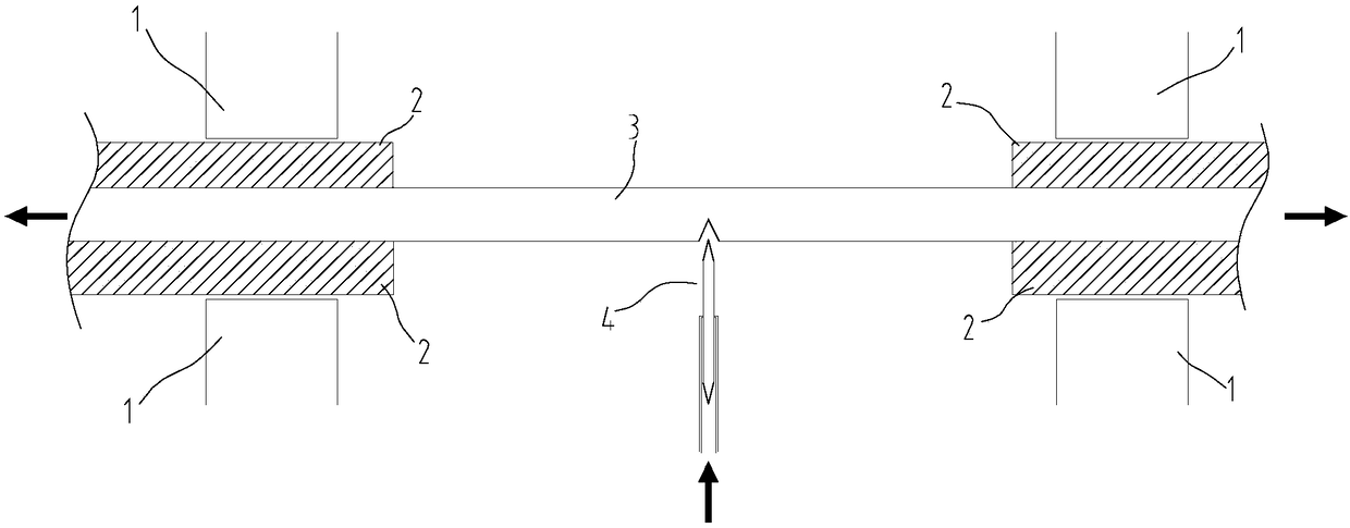
[0008] The second is to pre-apply tension on both sides of the optical fiber, and then enter the knife to generate a knife edge. Since the
diameter of the optical fiber is only 125 microns, and after the coating is stripped off, it becomes very brittle and fragile. Because the
diameter is too small, it must be removed. Clamping without clamping off requires high requirements for
material selection. When clamping it, the clamping surface needs to be very smooth and at the same time have enough friction, which is very difficult. At present, most of them use High-precision and expensive v-groove clamping surface (fixture, the difference from the first method is that it clamps the surface of the optical fiber and pulls it on both sides at the same time, so the clamping surface is not an elastic body, but a hard surface with high precision ); for the cutter part, only ultrasonic cutters and some very high-end cutters use this method at present, and the price is dozens of times more expensive than the fiber optic cutter using the first method
[0009] Even if these high-precision and expensive v-groove clamping surfaces are used, they must be cleaned at any time during use. A little dust falls on the clamping surface. When clamping, the clamping surface is squeezed by dust, which will affect the corresponding The part in contact with dust will cause greater stress, which will cause the fiber to break, so the
operating environment is extremely demanding;
[0010] In addition to this problem, the non-ultrasonic tool is to press the optical fiber surface under the action of pressure after the optical fiber is tightened. Therefore, the requirements for the tool are also very high. At present, only a few manufacturers can process this. This kind of precision tool, so this kind of tool is not popular in the market at present, the
processing difficulty is too high and the price is expensive
[0011] At the same time, in some patents, a cutting method without stripping the coating is also mentioned. However, the current mainstream of optical fiber fusion splicers can only use the optical fiber after stripping the coating. Most fiber optic fusion splicers cannot be used;
[0012] Even if this method is used to cut the optical fiber first and then peel off the coating, after cleaning, there is a
high probability that the coating residue will accumulate on the end face of the optical fiber, which is difficult to remove even with
alcohol, and the power required for pre-
discharge cleaning is very low. Difficult to control, usually the coating residue will be burned into protrusions on the end face of the optical fiber, which will affect the quality of the fusion splicing, resulting in a large loss in the
transmission rate of the subsequent optical fiber, especially for the
trunk line, which cannot bear such a large loss

