
Method for controlling unmanned aerial vehicle, flight controller and unmanned aerial vehicle

A technology of unmanned aerial vehicles and flight controllers, applied in the field of unmanned aerial vehicles, can solve problems such as failure of obstacle avoidance function, failure to detect obstacles, limited detection angle range, etc., and achieve the effect of avoiding flight accidents

Inactive Publication Date: 2018-10-23
SZ DJI TECH CO LTD
View PDF23 Cites 1 Cited by
  • Summary
  • Abstract
  • Description
  • Claims
  • Application Information

AI Technical Summary

Problems solved by technology

[0002] UAVs are equipped with detection sensors to detect obstacles to achieve obstacle avoidance. However, the detection sensors are usually only fixed in front of UAVs, and the range of detection angles is limited. When UAVs are not facing straight ahead but have When flying at a certain offset angle, obstacles cannot be detected because the route range in the flight direction exceeds the effective detection range of the detection sensor, resulting in the failure of the obstacle avoidance function

Method used


Image

  • Method for controlling unmanned aerial vehicle, flight controller and unmanned aerial vehicle
  • Method for controlling unmanned aerial vehicle, flight controller and unmanned aerial vehicle
  • Method for controlling unmanned aerial vehicle, flight controller and unmanned aerial vehicle

Examples


Embodiment Construction

[0053] Embodiments of the present invention are described in detail below, examples of which are shown in the drawings, wherein the same or similar reference numerals designate the same or similar elements or elements having the same or similar functions throughout. The embodiments described below by referring to the figures are exemplary only for explaining the present invention and should not be construed as limiting the present invention.

[0054] In the description of the present invention, it should be understood that the terms "first" and "second" are used for description purposes only, and cannot be interpreted as indicating or implying relative importance or implicitly indicating the quantity of indicated technical features. Thus, a feature defined as "first" or "second" may explicitly or implicitly include one or more of said features. In the description of the present invention, "plurality" means two or more, unless otherwise specifically defined.

[0055] In the de...


PUM


Abstract

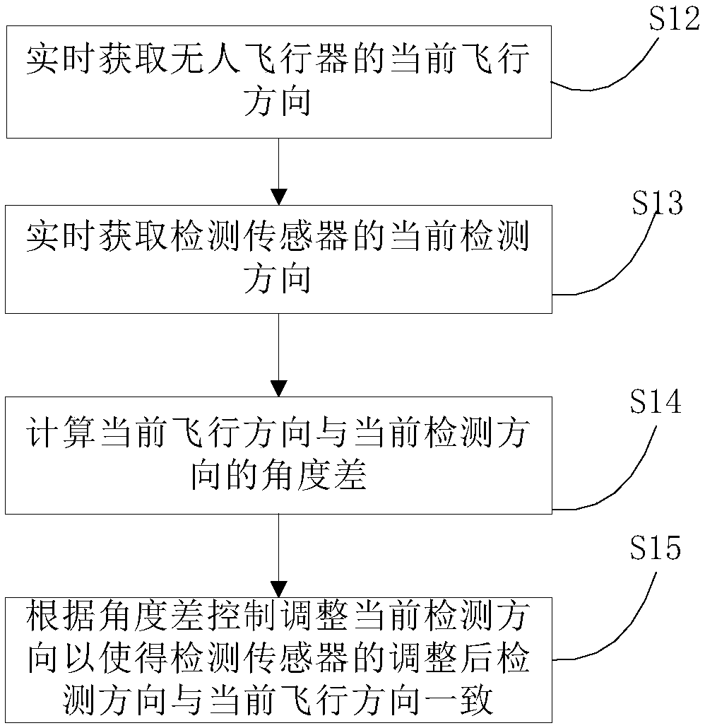
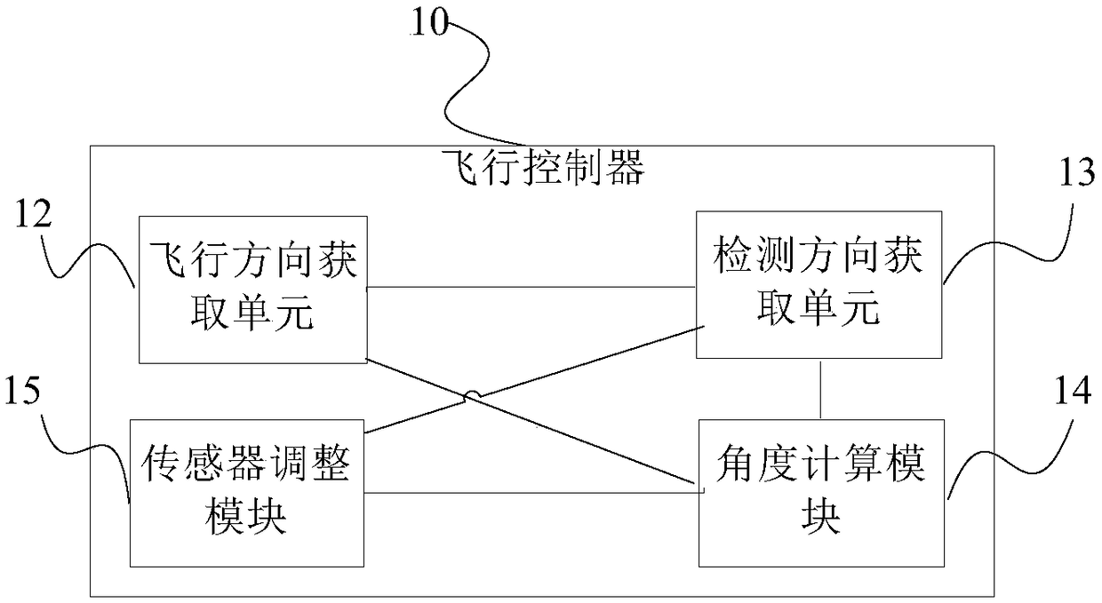
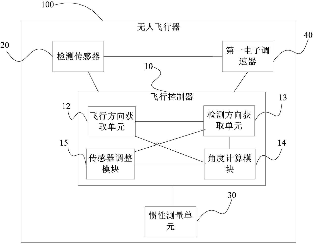
A method for controlling an unmanned aerial vehicle (100), a flight controller (10), and an unmanned aerial vehicle (100). The method for controlling the unmanned aerial vehicle (100) comprises the following steps: acquiring the current flight direction of the unmanned aerial vehicle (100) in real time (S12); acquiring the current detection direction of a detection sensor (20) in real time (S13);calculating an angle difference between the current flight direction and the current detection direction (S14); and controlling and adjusting the current detection direction according to the angle difference such that the adjusted detection direction of the detection sensor (20) is consistent with the current flight direction (S15). The detection sensor (20) can rotate in various directions, and the adjusted detection direction of the detection sensor (20) is always consistent with the current flight direction; and the detection range of the detection sensor (20) always covers the range of a route in the current flight direction of the unmanned aerial vehicle (100), so as to effectively detect an obstacle in the flight direction of the unmanned aerial vehicle (100), thereby avoiding a flight accident caused by collision with the obstacle.

Description

technical field [0001] The invention relates to the technical field of unmanned aerial vehicles, in particular to a control method for an unmanned aerial vehicle, a flight controller and the unmanned aerial vehicle. Background technique [0002] UAVs are equipped with detection sensors to detect obstacles to achieve obstacle avoidance. However, the detection sensors are usually only fixed in front of UAVs, and the range of detection angles is limited. When UAVs are not facing straight ahead but have When flying at a certain offset angle, obstacles cannot be detected because the route range in the flight direction exceeds the effective detection range of the detection sensor, resulting in the failure of the obstacle avoidance function. Contents of the invention [0003] Embodiments of the present invention provide a control method, a flight controller and an unmanned aerial vehicle. [0004] The control method of the unmanned aerial vehicle of the embodiment of the present...

Claims


Application Information

Patent Timeline
Patent Type & Authority Applications(China)
IPC IPC(8): G05D1/10
CPCG05D1/101B64U30/20G08G5/0013G08G5/0069G08G5/045B64U2201/00G05D1/106G08G5/0039B64U2201/10B64U2201/20
Inventor 宋亮蒋宁王浩飞
Owner SZ DJI TECH CO LTD
Learn More