A user emotion display method, system and user emotion display device

A display method and technology of a display system, applied in the field of live video, can solve the problems that live broadcast users are not attractive, cannot be a live platform to mine information, and interactive information is too random.

Active Publication Date: 2021-04-02
SHENZHEN H&T DATA RESOURCES & CLOUD TECH LTD
View PDF7 Cites 0 Cited by
  • Summary
  • Abstract
  • Description
  • Claims
  • Application Information

AI Technical Summary

Problems solved by technology

[0004] However, in the field of existing network live broadcasting technology, the focus of technology development is still on live streaming data or optimizing network transmission, and it does not provide corresponding experience and better interaction for the content of live broadcast channels.
Moreover, for many live broadcast viewers who are introverted and not good at expressing, even if the live broadcast interactive session is set up, it is difficult for the introverted viewers to participate in the live broadcast interactive session
Moreover, the interactive information of live viewers in the interactive link is too random, the interactive link is not very attractive to live broadcast users, and the interactive process cannot become the mineable information for the live broadcast platform that guides the live broadcast content

Method used


Image

  • A user emotion display method, system and user emotion display device
  • A user emotion display method, system and user emotion display device
  • A user emotion display method, system and user emotion display device

Examples


Embodiment 1

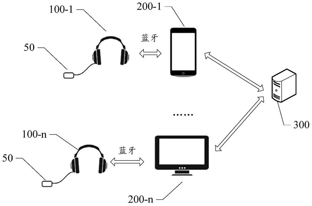
[0097] The following describes the user emotion display system in detail.

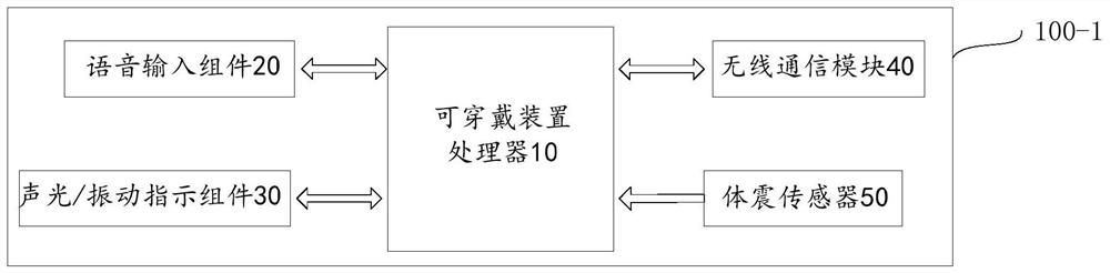
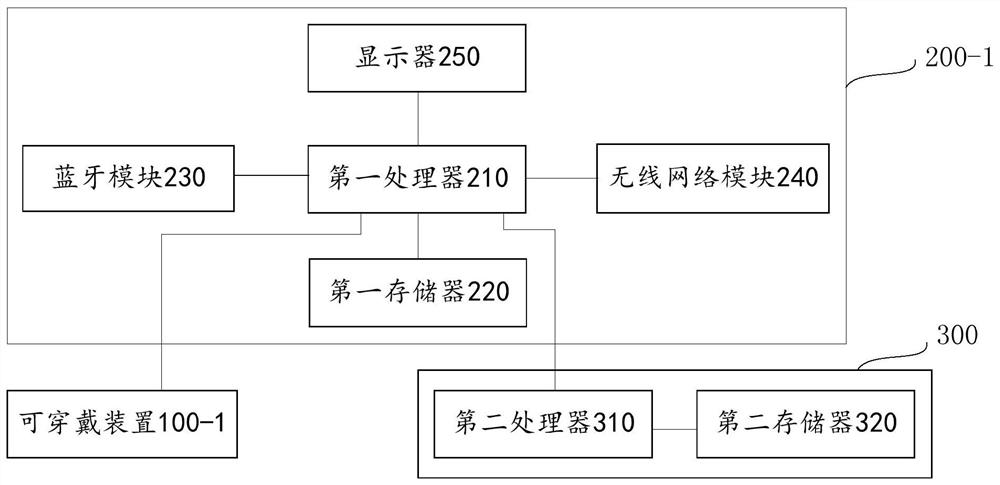
[0098] like figure 2 As shown, the wearable device 100 - 1 includes a wearable device processor 10 with memory, a voice input component 20 , an acousto-optic / vibration indicating component 30 , a wireless communication module 40 and a body shock sensor 50 . The wearable device processor 10 is respectively connected to the voice input component 20, the acousto-optic / vibration indication component 30, the wireless communication module 40 and the body vibration sensor 50, and the connection may be a communication connection. The wearable device 100 - 1 communicates with the wirelessly connected display terminal 200 - 1 through the wireless communication module 40 . Wherein, the structures of the other wearable devices 100-2 to 100-n are the same as the structure of the wearable device 100-1, so details are not described here.

[0099] First, the body shock sensor 50, such as an acceleration sensor or a...

Embodiment 2

[0114] Please refer to Image 6 , is a schematic flowchart of a method for displaying user emotions provided in an embodiment of the present application, the method for displaying user emotions is applied to a system for displaying user emotions, and the system for displaying user emotions includes a wearable device, a display terminal, and a cloud server. The method for displaying user emotions can be executed by the cloud server, wearable device or display terminal, which is not limited in this embodiment of the present application.

[0115] Wherein, the user emotion display method mainly includes the following steps:

[0116] Step 101: Obtain biological vibration information collected by the wearable device.

[0117] Wherein, the biometric information may be the biometric information of the user collected by the wearable device based on time domain. After the wearable device collects the biological vibration information, it can send the biological vibration information to...

Embodiment 3

[0135] Please refer to Figure 8 , is a schematic diagram of a user emotion display device provided in an embodiment of the present application. The user emotion display device may be configured in a cloud server.

[0136] refer to Figure 8 , the user emotion display device 80 includes:

[0137] The biological vibration information acquisition unit 801 is configured to acquire the biological vibration information collected by the wearable device.

[0138] Wherein, the biometric information may be the biometric information of the user collected by the wearable device based on time domain. After the wearable device collects the biological vibration information, it can send the biological vibration information to the display terminal, and then the display terminal forwards the biological vibration information, and the biological vibration information The acquisition unit 801 can receive the biological vibration information forwarded by the display terminal, so as to acquire ...


PUM


Abstract

The present application relates to the technical field of live video, and discloses a user emotion display method, device and system. The user emotion display system includes a wearable device, a display terminal and a cloud server. The method includes: acquiring biological vibrations collected by the wearable device. extracting shock information from biological shock information, and establishing shock information frames according to the shock information; performing frequency domain analysis on each shock information frame in the shock information frames to extract the shock information The cardiac shock characteristic information; according to the cardiac shock characteristic information, query the cardiac shock characteristic information and the emotional degree comparison database, determine the target emotional degree, and send the target emotional degree to the display terminal, so that the display terminal can display it in real time The target emotional degree, the target emotional degree is the first emotional degree corresponding to the cardiac shock feature information. Therefore, the emotion of the target object can be known in real time by holding the display terminal through the first emotion degree.

Description

technical field [0001] The present application relates to the field of live video technology, and in particular to a method for displaying user emotions, a device for displaying user emotions, and a system for displaying user emotions using the method for displaying user emotions. Background technique [0002] With the development of network transmission technology, wireless near-field communication technology and mobile terminal data processing technology, online live broadcast, such as live broadcast of sports events or live broadcast of cable video, has become an increasingly popular way for users to watch programs. Users can watch their favorite direct programs anytime and anywhere with the help of wireless network data transmission. [0003] Online video live broadcast is a high-end form of video media. From the perspective of information dissemination, live broadcasting allows users to connect with the live broadcast site in real time, providing a real and direct vide...

Claims


Application Information

Patent Timeline
Patent Type & Authority Patents(China)
IPC IPC(8): H04N21/2187H04N21/258H04N21/41H04N21/422H04N21/431H04N21/488H04N21/8547A61B5/16
CPCA61B5/165H04N21/2187H04N21/25866H04N21/4126H04N21/42201H04N21/4316H04N21/4888H04N21/8547
Inventor 龚梅军梁杰范欣薇孟亚斌刘洪涛
Owner SHENZHEN H&T DATA RESOURCES & CLOUD TECH LTD
Why Eureka
Try Eureka