Microfluidic chip and analytical instrument with same

A microfluidic chip and chip technology, applied in the field of medical devices, can solve problems such as low production efficiency and complicated preparation, and achieve the effects of improving production efficiency, reducing the difficulty of production technology, and being convenient to use

Pending Publication Date: 2018-10-26
GUANGZHOU WONDFO BIOTECH
View PDF7 Cites 14 Cited by
  • Summary
  • Abstract
  • Description
  • Claims
  • Application Information

AI Technical Summary

Problems solved by technology

The existing microfluidic chips mainly focus on qualitative detection, and there are few microfluidic chips for quantitative detection, and the preparation of existing quantitative microfluidic chips is complicated and the production efficiency is low

Method used


Image

  • Microfluidic chip and analytical instrument with same
  • Microfluidic chip and analytical instrument with same
  • Microfluidic chip and analytical instrument with same

Examples


Embodiment 1

[0036] This embodiment provides a microfluidic chip, the microfluidic chip includes a chip body, and a sample inlet, an air inlet, a liquid driving force inlet, an air branch channel, a main fluid channel and Multiple functional chambers; detailed below.

[0037] In this embodiment, the main fluid channel communicates with multiple functional chambers to guide fluid flow between the functional chambers. The liquid driving force inlet is used to connect the liquid driving device to drive liquid to flow in the main fluid channel and the plurality of functional chambers.

[0038]In this embodiment, the functional chamber has at least the function of accommodating. Preferably, the functional chamber has other functions besides the accommodating function. The external necessary components (these necessary components can be fixed outside the chip, need not be arranged in the chip or its surface) are jointly realized.

[0039] In this embodiment, at least one liquid quantitative ch...

Embodiment 2

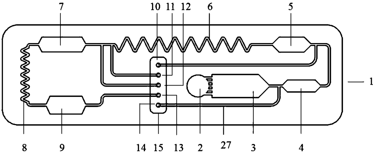
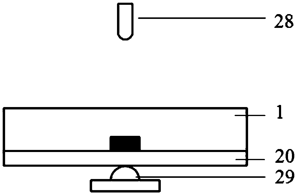
[0056] Please refer to Figure 1 to Figure 5 , this embodiment provides a chemiluminescent microfluidic chip, which includes a chip body, and a sample inlet 2, a liquid driving force inlet 13, a substrate luminescence liquid inlet 11, a cleaning solution inlet 12, Substrate luminescent liquid branch channel 17, cleaning liquid branch channel 18, main fluid channel and multiple functional chambers; detailed description will be given below.

[0057] In this embodiment, the main fluid channel communicates with multiple functional chambers to guide fluid flow between the functional chambers.

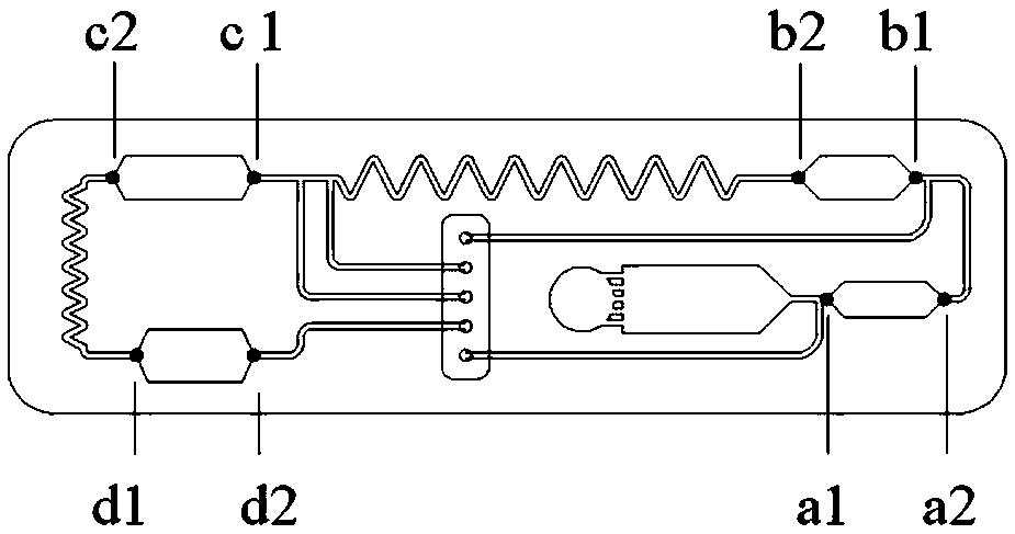
[0058] The functional chamber includes a sample quantification area 4 , an enzyme-labeled primary antibody embedding area 5 , a magnetic-labeled secondary antibody embedding area 7 and a chemiluminescent detection area 9 connected in sequence through the main fluid channel.

[0059] Among them, the enzyme-labeled primary antibody embedding area 5 is embedded with an enzyme-labeled primary a...

Embodiment 4

[0078] The description about the liquid quantification chamber in Embodiment 4 is applicable to the above-mentioned liquid quantification chamber (including the magnetic label secondary antibody embedding area 7, the enzyme-labeled primary antibody embedding area 5 and the sample quantification chamber 4), here No longer.


PUM

PropertyMeasurementUnit
widthaaaaaaaaaa
heightaaaaaaaaaa
widthaaaaaaaaaa

Abstract

The invention discloses a microfluidic chip. The microfluidic chip comprises a main chip body, a sample inlet, an air inlet, a liquid driving force inlet, a branched air channel, a main fluid channeland multiple functional cavities, wherein the sample inlet, the air inlet, the liquid driving force inlet, the branched air channel, the main fluid channel and the functional cavities are formed in the main chip body; the main fluid channel is communicated with the functional cavities, and the liquid driving force inlet is used for being connected with a liquid driving device capable of driving fluid to flow in the main fluid channel and the functional cavities. The specific liquid quantifying cavities are used for recognizing, positioning and quantifying liquid samples, the manufacturing technological difficulty of the chip is lowered, the accuracy of quantification is improved, and the microfluidic chip is particularly suitable for quantifying and testing full-blood samples.

Description

technical field [0001] The invention relates to the field of medical devices, in particular to a microfluidic chip and an analysis instrument containing it. Background technique [0002] In Vitro Diagnosis (In Vitro Diagnosis, IVD) refers to taking out samples (blood, body fluids, tissues, etc.) from the human body for detection and analysis to diagnose diseases. The detection process requires corresponding instruments and reagents, which consist of in vitro diagnostic system. In vitro diagnostic systems are roughly divided into two types; one is represented by the testing center laboratory, which has system modularization, automation, and pipeline-style sample testing, so it also has high-throughput, high-efficiency, and high-sensitivity. Advantages, but the entire system also has the disadvantages of high cost, large volume, and professional operation. It is mainly used in large hospitals. The other one is represented by point-of-care testing (POCT). Its system is integr...

Claims


Application Information

Patent Timeline
Patent Type & Authority Applications(China)
IPC IPC(8): B01L3/00G01N33/48
CPCG01N33/48B01L3/5027B01L3/502753B01L2200/0621B01L2200/0605B01L2300/021G01N33/5302B01L3/502738B01L2400/0694B01L2300/087B01L2300/0816B01L2300/0681B01L2400/0487B01L3/502715B01L2200/0689B01L2300/0663B01L2300/0883B01L2400/0478
Inventor 蒙玄万惠芳胡海升李文美
Owner GUANGZHOU WONDFO BIOTECH
Why Eureka
Try Eureka