Punching die and punching method for rectangular tube

A technology for punching rectangular tubes, applied in the direction of perforating tools, manufacturing tools, feeding devices, etc., can solve the problems of rectangular tube side wall deformation, affecting punching quality, and inability to punch holes, so as to improve quality and improve punching The effect of positioning accuracy and avoiding misalignment

Pending Publication Date: 2018-10-26
安徽恒兴装备材料有限公司
View PDF1 Cites 0 Cited by
  • Summary
  • Abstract
  • Description
  • Claims
  • Application Information

AI Technical Summary

Problems solved by technology

[0006] Aiming at the problem that the pipe punching die in the prior art will cause the side wall of the rectangular pipe to deform when punching the rectangular pipe, affect the punching quality, or even fail to punch the hole, the present invention provides a rectangular pipe punching die and In the punching method, a lower mold core is set in the lower mold assembly. When punching, the rectangular tube is placed on the lower mold core, which avoids the deformation of the rectangular tube by stamping. In addition, the lower mold core also plays a guiding role for the insertion of the rectangular tube. , to avoid the deviation of the rectangular tube, improve the positioning accuracy of the punching hole, and greatly improve the quality of the punching process

Method used


Image

  • Punching die and punching method for rectangular tube
  • Punching die and punching method for rectangular tube
  • Punching die and punching method for rectangular tube

Examples


Embodiment 1

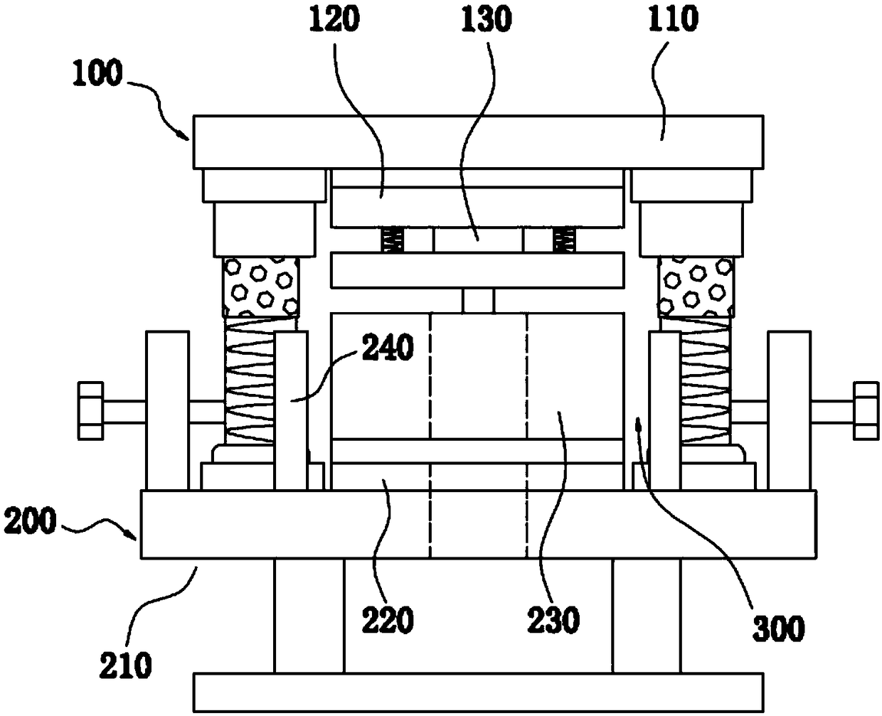
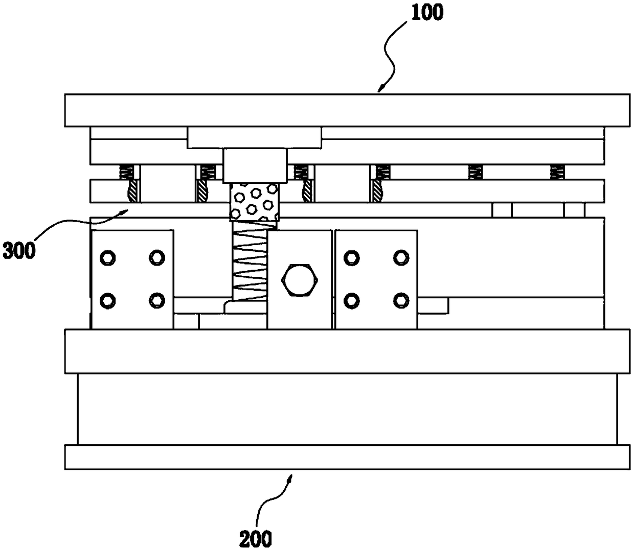
[0050] A rectangular tube punching die, such as figure 1 , 2 As shown, an upper mold assembly 100 and a lower mold assembly 200 are included.

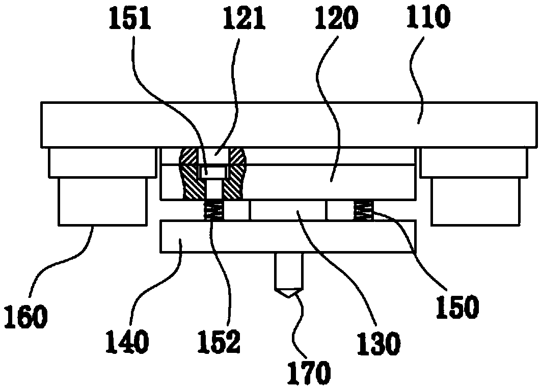
[0051] Such as figure 1 , 2 As shown, the upper mold assembly 100 includes an upper mold plate 110, an upper mold core seat 120 and several upper mold cores 130, the upper mold core base 120 is fixed on the bottom of the upper mold plate 110, and the upper mold core 130 is fixed At the lower end of the upper mold core base 120; the upper mold plate 110 and the upper mold core base 120 are both flat plates; the upper mold core 130 can be cylindrical or polygonal, or other Cylindrical shape with irregular cross-section, such as figure 1 , 2 As shown, the upper mold core 130 is cylindrical and is used to process circular holes; the number and arrangement of the upper mold core 130 are set according to the number and position of the processed holes, which can be one or two or three Above, when there are more than two upper mold cores...

Embodiment 2

[0057] A kind of rectangular pipe punching die of the present embodiment, basic structure is the same as embodiment 1, difference and improvement are, as image 3 , 4 , 5, the lower mold assembly 200 is provided with a guide column 260, and the guide column 260 is fixed on the support seat 210; as Figure 6 , 7 As shown in , 8 , the upper mold assembly 100 is provided with a guide sleeve 160 matched with the guide column 260 , and the guide sleeve 160 is fixed on the bottom of the upper mold 110 . The number of the guide post 260 and the guide sleeve 160 is more than one. In this embodiment, there are two guide posts 260 and the guide sleeve 160, and they are arranged symmetrically, so that the positioning and guidance are more stable.

[0058] A kind of rectangular pipe punching die of this embodiment, by setting the guide sleeve 160 and the guide post 260 that cooperate with each other between the upper die assembly 100 and the lower die assembly 200, can play the mold cla...

Embodiment 3

[0060] A kind of rectangular pipe punching die of the present embodiment, basic structure is the same as embodiment 1 or 2, and difference and improvement are, as Figure 6 , 7 As shown in . The positioning mechanism 250 can be a manually adjusted positioning mechanism, or a hydraulically driven automatic positioning mechanism, or other feasible positioning mechanisms. In this embodiment, it is a manually adjusted positioning mechanism, which has a simple structure and low cost;

[0061] The number of the positioning mechanism 250 is more than one; in this embodiment, as Figure 6 , 7 , 8, there are two manually adjustable positioning mechanisms 250, which are symmetrically arranged on the left and right sides of the lower core seat 220, and are located between the front and rear core holes 231. When only a single hole needs to be punched, By adjusting the position limit of the positioning mechanism 250, the insertion depth of the end of the rectangular tube to be processed...


PUM


Abstract

The invention discloses a punching die and a punching method for a rectangular tube, and relates to the field of square steel tube processing and producing. The die includes an upper die assembly anda lower die assembly; the upper die assembly comprises an upper template, an upper die core seat and a plurality of upper die cores; the upper die core seat is fixed at the bottom of the upper template, and the upper die cores are fixed at the lower end of the upper die core seat; the lower die assembly comprises a supporting seat, a lower die core seat, a lower die core and a plurality of baffles; the lower die core seat and the baffles are fixed on the supporting seat, the baffles are symmetrically arranged on the two sides of the lower die core seat, the lower die core is fixed on the lowerdie core seat, and a plurality of die core holes matched with the upper die cores are formed in the lower die core; and a material storing cavity is formed in the outer edge of the lower die core after the upper die assembly and the lower die assembly are buckled up and down. According to the punching die, the lower die core is arranged in the lower die assembly, the rectangular tube is arrangedon the lower die core in a sleeving mode, and the rectangular tube is prevented from deformation due to punching; and a guiding function is also achieved by inserting the rectangular tube in the lowerdie core, the deflection of the rectangular tube is avoided, the positioning accuracy of the punching is high, and the punching quality is greatly improved.

Description

technical field [0001] The invention relates to the field of processing and production of square steel pipes, in particular to a rectangular pipe punching die and a punching method. Background technique [0002] Rectangular tube is a hollow square cross-section light-weight thin-walled steel tube, also known as cold-rolled steel profile, usually using Q235 hot-rolled or cold-rolled strip or coil as the base material, after cold-bending The section steel with square cross-section shape and size made by frequency welding is divided into seamless steel pipe and welded steel pipe, and seamless steel pipe is divided into hot-rolled seamless square tube, cold-drawn seamless square tube, and extruded seamless square tube. Rectangular tubes are widely used in construction, machinery manufacturing, power engineering and other fields. For example, shipbuilding, solar power generation supports, steel structure engineering, agricultural and chemical machinery, glass curtain walls, autom...

Claims


Application Information

Patent Timeline
IPC IPC(8): B21D28/28B21D28/34B21D43/00
CPCB21D28/28B21D28/34B21D43/003
Inventor 汪国华童效玲
Owner 安徽恒兴装备材料有限公司
Why Eureka
Try Eureka