Low-energy-consumption large fluidized powder warehouse and discharge method thereof
A fluidized powder, low energy consumption technology, applied in the direction of large containers, loading/unloading, containers, etc., can solve the problems of increasing the working intensity of lifting equipment dust collection equipment, unstable discharge flow, energy loss, etc. The material flow is stable and easy to control, the discharge efficiency is improved, and the energy consumption of the material is reduced.
- Summary
- Abstract
- Description
- Claims
- Application Information
AI Technical Summary
Problems solved by technology
Method used
Image
Examples
Embodiment 1
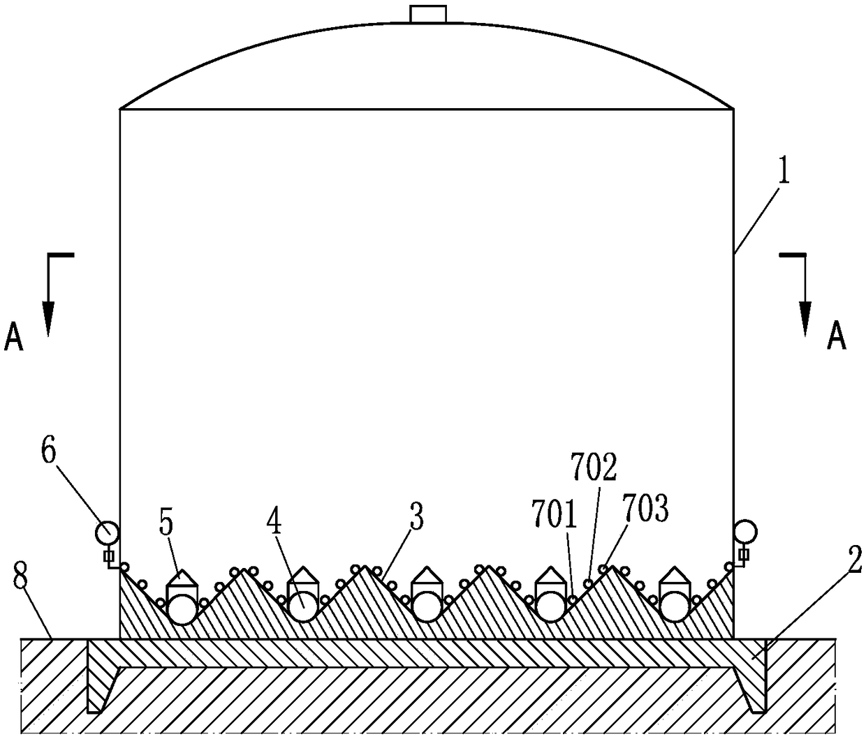
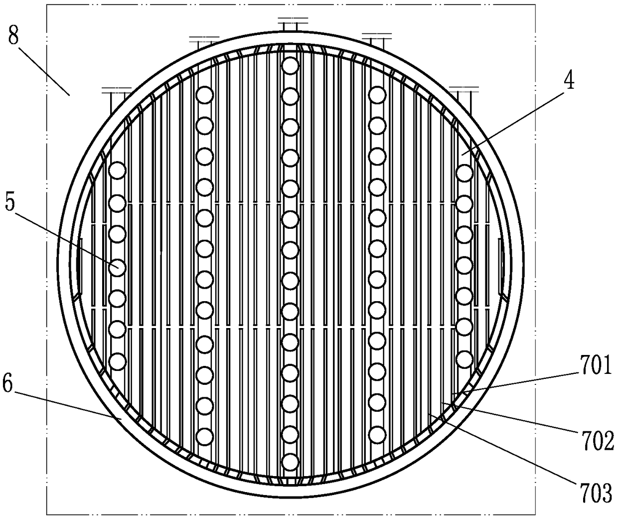
[0020] Such as figure 1 and figure 2 The low-energy consumption large-scale fluidized powder storage of the present invention shown in the present invention includes a storage body 1 and a storage bottom 2, the storage bottom 2 is flush with the ground 8, five V-shaped grooves 3 are arranged on the storage bottom 2, and the V-shaped groove 3 The material delivery pipe 4 is arranged at the bottom of the V-shaped groove, and the material flow aid device is arranged on the slope surface on both sides of the V-shaped groove. The material flow aid device is specifically a pneumatic fluidization rod. 6 connected, the material flow aid device 6 is arranged parallel to the material conveying pipe 4, and there are three groups of material flow aid devices, including the first group of material flow aid devices 701 located at the bottom of the V-shaped groove, and the upward and sequentially arranged The second group of material flow aid devices 702 and the third group of material flo...
Embodiment 2
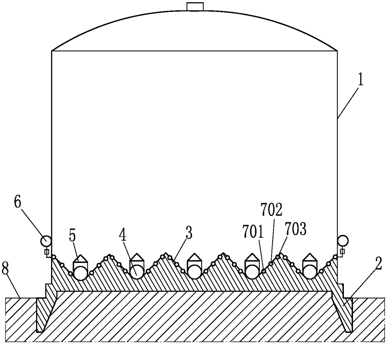
[0031] Such as image 3 The difference between the low-energy consumption large-scale fluidized powder storage of the present invention and the first embodiment is that the upper surface of the storage bottom 2 is slightly higher than the ground 8; in addition, all material flow aid devices are embedded in the V-shaped groove 3 In the grooves set on the surface of the slopes on both sides, that is, the first group of material flow aid devices 701, the second group of material flow aid devices 702 and the third group of material flow aid devices 703 are all embedded in the slopes on both sides of the V-shaped groove 3 In the groove set on the surface.
[0032] The discharging method of the technical solution described in this example is basically the same as that described in Example 1, and will not be repeated here. Compared with Embodiment 1, the upper surface of the reservoir bottom 2 is slightly higher than the ground 8, which is beneficial to waterproof and moisture-proof...
PUM
 Abstract
Description
Claims
Application Information
 - R&D
- Intellectual Property
- Life Sciences
- Materials
- Tech Scout
- Unparalleled Data Quality
- Higher Quality Content
- 60% Fewer Hallucinations
Browse by: Latest US Patents, China's latest patents, Technical Efficacy Thesaurus, Application Domain, Technology Topic, Popular Technical Reports.
© 2025 PatSnap. All rights reserved.Legal|Privacy policy|Modern Slavery Act Transparency Statement|Sitemap|About US| Contact US: help@patsnap.com


