
Constructed wetland system for sewage treatment

A technology for constructed wetland system and sewage treatment, applied in biological water/sewage treatment, water/sludge/sewage treatment, chemical instruments and methods, etc., can solve the problem of shortened operating life, reduced wetland water conservancy load, easy blockage of subsurface wetlands, etc. problems, to achieve the effect of reducing clogging problems, high processing load, and eliminating clogging problems

Pending Publication Date: 2018-10-26
上海景青绿环境科技有限公司
View PDF0 Cites 0 Cited by
  • Summary
  • Abstract
  • Description
  • Claims
  • Application Information

AI Technical Summary

Problems solved by technology

[0003] Subsurface flow wetlands are mainly divided into three categories: vertical subsurface flow wetlands, horizontal subsurface flow wetlands, and mixed subsurface flow wetlands. For current subsurface flow wetlands, clogging is a natural process in the operation process and is also a difficult problem to be considered in design and management. According to the United States According to the investigation of more than 100 operating constructed wetlands by the Environmental Protection Agency, nearly half of the wetland systems have been blocked within five years of being put into use. serious impact on operation
[0004] Therefore, there is an urgent need to overcome the technical problem that subsurface flow wetlands are easily blocked in the prior art

Method used


Image

  • Constructed wetland system for sewage treatment
  • Constructed wetland system for sewage treatment

Examples


Embodiment 1

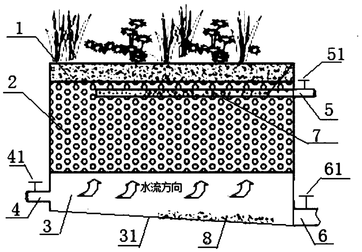
[0024] A constructed wetland system for sewage treatment, such as figure 1 As shown, it includes a vertical subsurface wetland and a reservoir 3 arranged below the vertical subsurface wetland; the bottom surface of the reservoir 3 is an inclined bottom surface 31, and the side wall of the reservoir connected to the higher end of the inclined bottom surface 31 is provided with an inlet. The water pipe 4 is provided with a recoil outlet pipe 6 on the side of the reservoir connected to the lower end of the inclined bottom surface 31, and an outlet water collection pipe 7 is provided in the vertical subsurface flow wetland, and the water outlet collection pipe 7 is connected with an outlet pipe 5.

[0025] In this embodiment, a water inlet valve 41 is provided on the water inlet pipe 4, a water outlet valve 51 is provided on the water outlet pipe 5, and a recoil outlet valve 61 is provided on the recoil outlet pipe 6, all of which can be switched independently. The lowest point of...

Embodiment 2

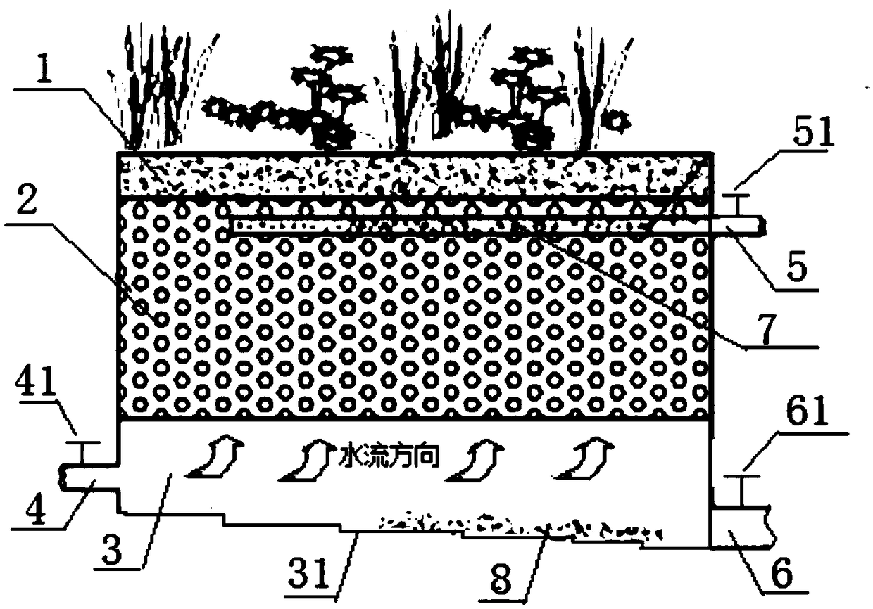
[0029] This embodiment is basically the same as Embodiment 1, the difference is that in this embodiment, the inclined bottom surface 31 is a stepped inclined bottom surface, such as figure 2 shown. The design of the stepped and inclined bottom surface avoids the accumulation of deposited solid impurities in the backwash water pipe during the sewage treatment process, thereby causing blockage of the backwash water pipe.


PUM


Abstract

The invention relates to a constructed wetland system for sewage treatment. The constructed wetland system comprises a vertical subsurface flow wetland and a reservoir (3) arranged below the verticalsubsurface flow wetland, wherein the bottom surface of the reservoir (3) is an inclined bottom surface (31); a water inlet pipe (4) is arranged on the side wall of the reservoir connected with a higher end of the inclined bottom surface (31); an outrush water outlet pipe (6) is arranged on the side face of the reservoir connected with a lower end of the inclined bottom surface (31); and a water outlet collection pipe (7) is arranged in the vertical subsurface flow wetland and connected with a water outlet pipe (5). Compared with the prior art, the constructed wetland system disclosed by the invention has the advantages that due to the ingenious structural design, the blockage problem in the sewage treatment process is reduced, and the system has a backwash function, so that the problem ofblockage is basically eliminated. The structure basically does not need to be damaged for maintenance in the using process, and the constructed wetland system is heavy in treatment load and is a high-efficiency constructed wetland system for sewage treatment.

Description

technical field [0001] The invention relates to the technical field of constructed wetlands, in particular to a constructed wetland system for sewage treatment. Background technique [0002] As a new type of sewage treatment ecosystem developed in the 1970s, constructed wetlands have been widely accepted all over the world for their advantages such as local construction and operation costs, strong decontamination capabilities, long service life, simple processes, and diverse combinations. application. [0003] Subsurface flow wetlands are mainly divided into three categories: vertical subsurface flow wetlands, horizontal subsurface flow wetlands, and mixed subsurface flow wetlands. For current subsurface flow wetlands, clogging is a natural process in the operation process and is also a difficult problem to be considered in design and management. According to the United States According to the investigation of more than 100 operating constructed wetlands by the Environmenta...

Claims


Application Information

Patent Timeline
IPC IPC(8): C02F3/32
CPCC02F3/32
Inventor 牟万东
Owner 上海景青绿环境科技有限公司
Learn More