Eureka AIR delivers breakthrough ideas for toughest innovation challenges, trusted by R&D personnel around the world.

Drying equipment for cleaning section of annealing unit

A technology of drying equipment and cleaning section, which is applied to heat treatment equipment, furnaces, heat treatment furnaces, etc. It can solve the problems of inconvenient use, inability to adapt to different specifications of metal wires, and imperfect functions, etc., and achieve the effect of easy use

Inactive Publication Date: 2018-10-26
SUZHOU JIN JU SONG MECHANICAL & ELECTRICAL CO LTD
View PDF0 Cites 4 Cited by
  • Summary
  • Abstract
  • Description
  • Claims
  • Application Information

AI Technical Summary

Problems solved by technology

[0004] The purpose of the present invention is to provide a drying equipment for cleaning section of annealing unit, to solve the problem that some existing drying equipment for cleaning section of annealing unit mentioned in the background art have imperfect functions and cannot adapt to metal wires of different specifications during use. Inconvenience

Method used


Image

  • Drying equipment for cleaning section of annealing unit
  • Drying equipment for cleaning section of annealing unit
  • Drying equipment for cleaning section of annealing unit

Examples


Embodiment Construction

[0017] The technical solutions in the embodiments of the present invention will be clearly and completely described below in conjunction with the accompanying drawings in the embodiments of the present invention. Obviously, the described embodiments are only a part of the embodiments of the present invention, rather than all the embodiments. Based on the embodiments of the present invention, all other embodiments obtained by those of ordinary skill in the art without creative work shall fall within the protection scope of the present invention.

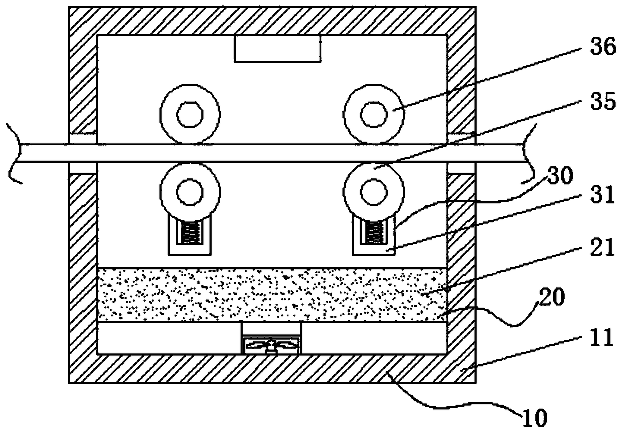
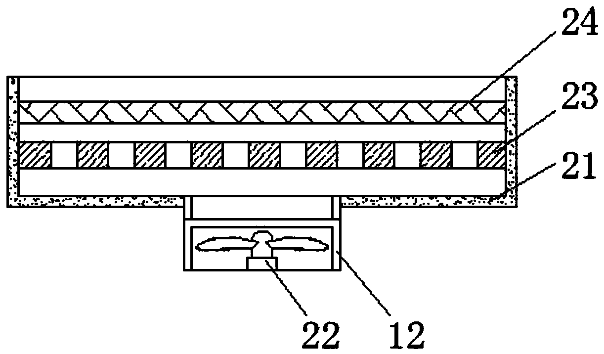
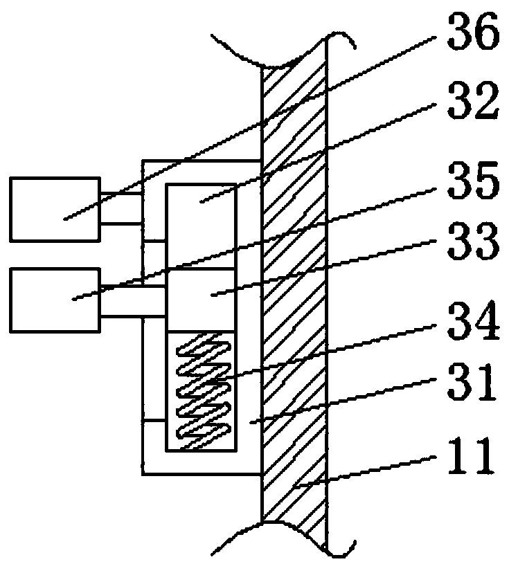
[0018] See Figure 1-3 , The present invention provides a technical solution: a drying equipment for the cleaning section of an annealing unit, comprising a protection assembly 10, a drying assembly 20 and an adjustment assembly 30. The protection assembly 10 is composed of a box body 11 and a shell 12, and the shell 12 is located in the box body. The inner wall of 11, and is fixedly connected to the lower surface of the inner wall of th...


PUM


Abstract

The invention discloses drying equipment for a cleaning section of an annealing unit. The drying equipment comprises a protective assembly, a drying assembly and an adjusting assembly. The protectiveassembly is composed of a box and a shell, and the shell is located on the inner wall of the box and fixedly connected with the lower surface of the inner wall of the box. The drying assembly is composed of a mounting box, a fan, a ventilation plate and an electric heating net, the mounting box is located in the box, and the left and right side faces of the mounting box are fixedly connected withthe left and right side faces of the inner wall of the box. When cleaned metal wires of different specifications enter the box, the metal wires penetrate through the positions between upper clamping rollers and lower clamping rollers, the upper clamping rollers are fixedly connected, the lower clamping rollers are movably connected, thus the metal wires downwards press the lower clamping rollers,the lower clamping rollers drive sliding blocks to downwards slide in sliding grooves through second connecting rods, the sliding blocks extrude springs, thus the metal wires of the different specifications can be dried, and using is facilitated.

Description

Technical field [0001] The invention belongs to the technical field of drying equipment, and specifically relates to a drying equipment for the cleaning section of an annealing unit. Background technique [0002] Annealing is a metal heat treatment process, which refers to slowly heating the metal to a certain temperature, keeping it for a sufficient time, and then cooling it at an appropriate speed. The purpose is to reduce hardness, improve machinability, eliminate residual stress, stabilize size, and reduce deformation and cracking tendency. [0003] Some of the existing drying equipment in the cleaning section of the annealing unit have imperfect functions and cannot adapt to different specifications of metal wires during use, which is inconvenient to use. Summary of the invention [0004] The purpose of the present invention is to provide a drying equipment for the cleaning section of an annealing unit to solve the imperfect function of some existing drying equipment for the c...

Claims


Application Information

Patent Timeline
Patent Type & Authority Applications(China)
IPC IPC(8): C21D9/52C21D1/26C23G3/02
CPCC21D9/525C21D1/26C23G3/027
Inventor 许云兰陈传辉陈传伟
Owner SUZHOU JIN JU SONG MECHANICAL & ELECTRICAL CO LTD
Why Eureka
Eureka Blog
Learn More