Gas drying apparatus removing heat by utilizing compressor and method

A compressor exhaust, compressor technology, applied in separation methods, chemical instruments and methods, dispersed particle separation, etc. Process requirements, the effect of improving energy utilization

Inactive Publication Date: 2014-03-26
SOUTHEAST UNIV
View PDF5 Cites 14 Cited by
  • Summary
  • Abstract
  • Description
  • Claims
  • Application Information

AI Technical Summary

Problems solved by technology

For freeze dryers, it requires additional power consumption; for adsorption dryers to achieve continuous operation, a certain amount of compressor displacement needs to be compromised, in other words, additional power consumption is increased

Method used


Image

  • Gas drying apparatus removing heat by utilizing compressor and method
  • Gas drying apparatus removing heat by utilizing compressor and method

Examples


Embodiment 1

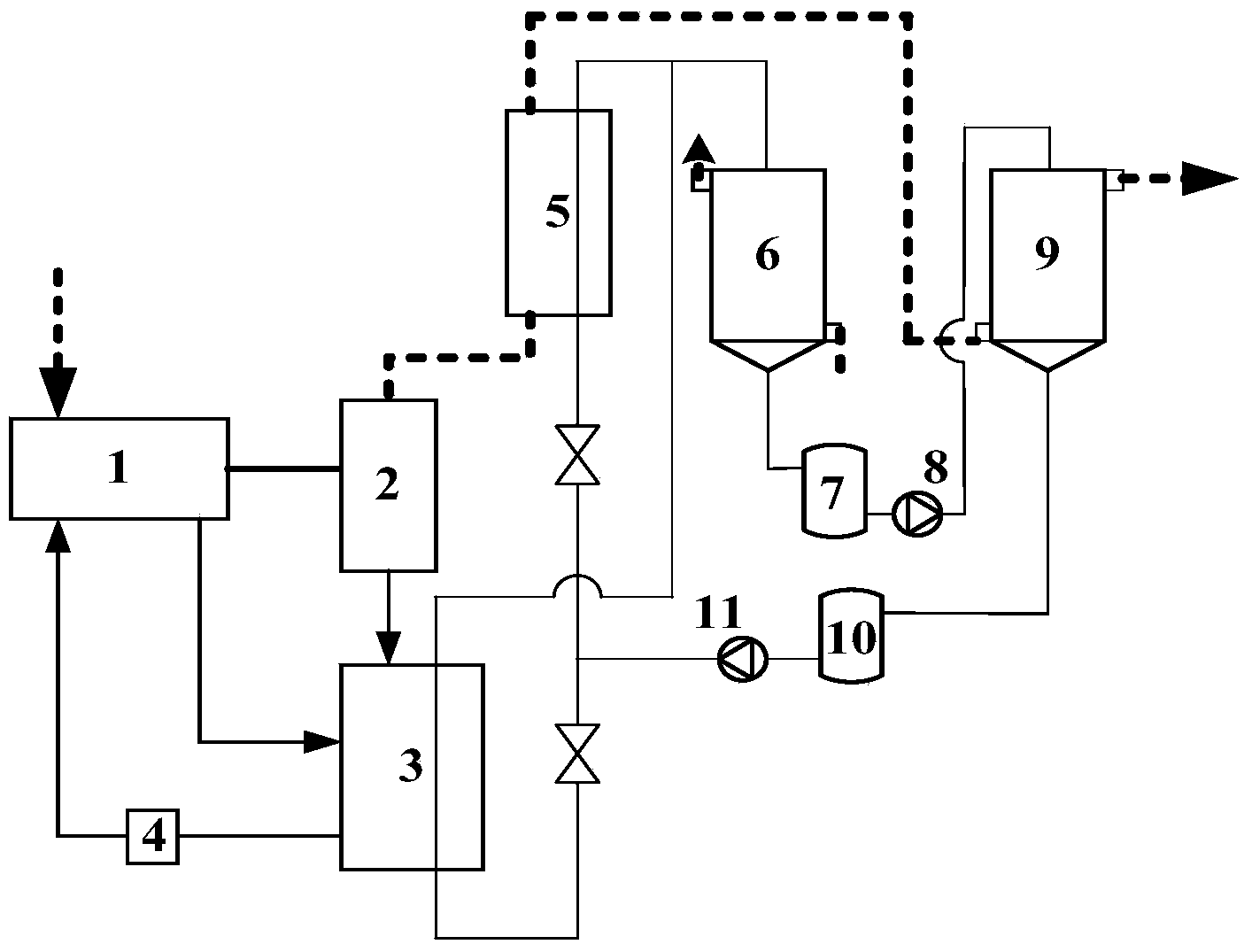
[0024] Embodiment 1: as figure 1 As shown, a gas drying method and device utilizing compressor exhaust heat mainly consists of a compressor host 1, an oil-gas separator 2, a lubricating oil heat recovery heat exchanger 3, an oil filter 4, and a compressor exhaust heat exchanger 5. It consists of a solution regenerator 6, a concentrated solution tank 7, a concentrated solution pump 8, a dehumidifier 9, a dilute solution tank 10, and a dilute solution pump 11. The lubricating oil heat recovery heat exchanger 3 and the inlet and outlet of the compressor exhaust heat exchanger 5 are respectively connected in parallel with the solution regenerator 6, the concentrated solution tank 7, the concentrated solution pump 8, the dehumidifier 9, the dilute solution tank 10, and the dilute solution tank 10. The solution pumps 11 are sequentially connected to form a cycle to form a solution loop. The dilute solution in the solution circuit is pumped to the lubricating oil heat recovery heat ...

Embodiment 2

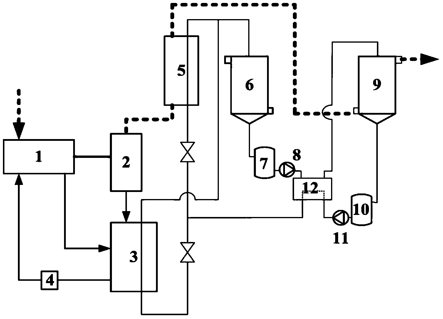
[0025] Embodiment 2: as figure 2As shown, a gas drying method and device utilizing compressor exhaust heat mainly consists of a compressor host 1, an oil-gas separator 2, a lubricating oil heat recovery heat exchanger 3, an oil filter 4, and a compressor exhaust heat exchanger 5. Solution regenerator 6, concentrated solution tank 7, concentrated solution pump 8, dehumidifier 9, dilute solution tank 10, dilute solution pump 11 and solution heat exchanger 12. After the lubricating oil heat recovery heat exchanger 3 and the compressor exhaust heat exchanger 5 are connected in parallel, they are connected with the solution regenerator 6, the concentrated solution tank 7, the concentrated solution pump 8, the solution heat exchanger 12, the dehumidifier 9, and the diluted solution. The solution tank 10 and the dilute solution pump 11 are sequentially connected to form a cycle to form a solution loop. In the solution loop, the dilute solution is first pumped to the solution heat e...


PUM


Abstract

The invention discloses a gas drying apparatus removing heat by utilizing a compressor and a method. The apparatus comprises the compressor (1), an oil-gas separator (2), a lubricating-oil heat recovery exchanger (3), an oil filterer (4), a compressor exhaust heat exchanger (5), a heat source regenerator (6), a solution storage tank (7), a concentrated solution pump (8), a dehumidifier (9), a dilute solution tank (10) and a dilute solution pump (11), wherein the gas outlet of the compressor (1) is connected with the inlet of the oil-gas separator (2), and the gas outlet of the oil-gas separator (2) is connected with the gas inlet of the compressor exhaust heat exchanger (5). The advantages comprise that the gas drying apparatus is capable of effectively recovering waste heat generated when an inflator runs, and the waste heat is utilized for drying processing of compressor exhausted gas and other gas resources, so that the compressor exhausted gas and other gas resources can satisfy the technological requirements; and the technology not only helps to reduce the consumption cost of energy, but also helps to reduce environmental pollution.

Description

technical field [0001] The invention belongs to the technical scope of comprehensive and high-efficiency utilization of energy, and relates to a method and device for drying gas by utilizing exhaust heat of a compressor, and specifically relates to a recovery and utilization system of exhaust heat of a compressor. Background technique [0002] Compressed air is one of the most widely used power sources in industry. Because of its many advantages such as safety, pollution-free, good adjustment performance, and convenient transportation, it is more and more widely used in modern industrial fields. But obtaining high-quality compressed air requires a lot of energy. In most production enterprises, the energy consumption of air compressors accounts for 10%-35% of the total power consumption. When the compressor is running, the input electric energy is mainly converted into two energy forms: the potential energy of increasing air pressure and the heat energy generated by mechani...

Claims


Application Information

Patent Timeline
Patent Type & Authority Applications(China)
IPC IPC(8): B01D53/26
Inventor 宋建忠张小松殷勇高徐国英姚启矿杨璨顾维维
Owner SOUTHEAST UNIV
Why Eureka
Try Eureka