Composite mass flowmeter

A mass flowmeter and composite technology, applied in the direction of indirect mass flowmeter, mass flow measuring device, measuring device, etc., can solve the problems of unstable outflow coefficient, low accuracy, easy to accumulate pollution, etc., and achieve reasonable structure, Easy installation and construction, high measurement accuracy

Inactive Publication Date: 2009-11-18
姚贤卿
View PDF0 Cites 13 Cited by
  • Summary
  • Abstract
  • Description
  • Claims
  • Application Information

AI Technical Summary

Problems solved by technology

In the 1980s, the Americans proposed a new throttling method, using the cone as the throttling element, which is suspended in the fluid pipeline, and the fluid flows along the pipe wall after being compressed and rectified by the cone in the center of the pipeline, overcoming the The disadvantages of the traditional differential pressure flowmeter's own structural defects, such as: unstable outflow coefficient, poor linearity, low repeatability, low accuracy, easy to accumulate dirt and wear, small range ratio, on-site High installation conditions
[0006] So far, most flowmeters can only measure the volume flow of single-phase media, but cannot measure the flow of two-phase and multi-phase fluids, and there are no products for dryness and density measurement
There is no precedent at home and abroad for a flowmeter that can measure two-phase flow or multiphase flow and simultaneously measure dryness and density

Method used


Image

  • Composite mass flowmeter
  • Composite mass flowmeter
  • Composite mass flowmeter

Examples


Embodiment 1

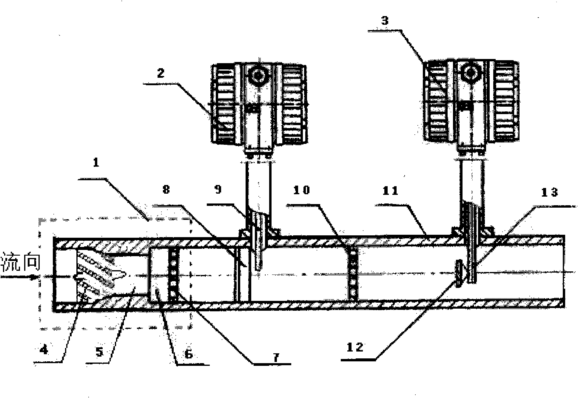
[0018] Example 1: from figure 1 It can be seen from the figure that a composite mass flowmeter includes a pipeline surface body 11, a vortex flow sensor 2, and a target flow sensor 3. On the meter body 11, the vortex generating body 8 and the vortex street detection probe 9 are installed in the pipeline meter body 11, the downstream of the pipeline meter body 11 is installed with a target flow sensor 3 for measuring flow velocity force, and the upstream end is equipped with a multiphase flow rectification device 1. The multi-phase flow rectification device 1 of the present invention is composed of a rotary vane wheel 4, a diameter-reducing area 5, a diffusion area 6, and a porous rectifier 7, and its shell and the pipe surface are integrally structured. That is to say, the shell of the multiphase flow rectification device 1 is a part of the pipeline surface body 11 .

[0019] The flow state of the two-phase flow or the multi-phase flow in the pipeline of the present inventio...

Embodiment 2

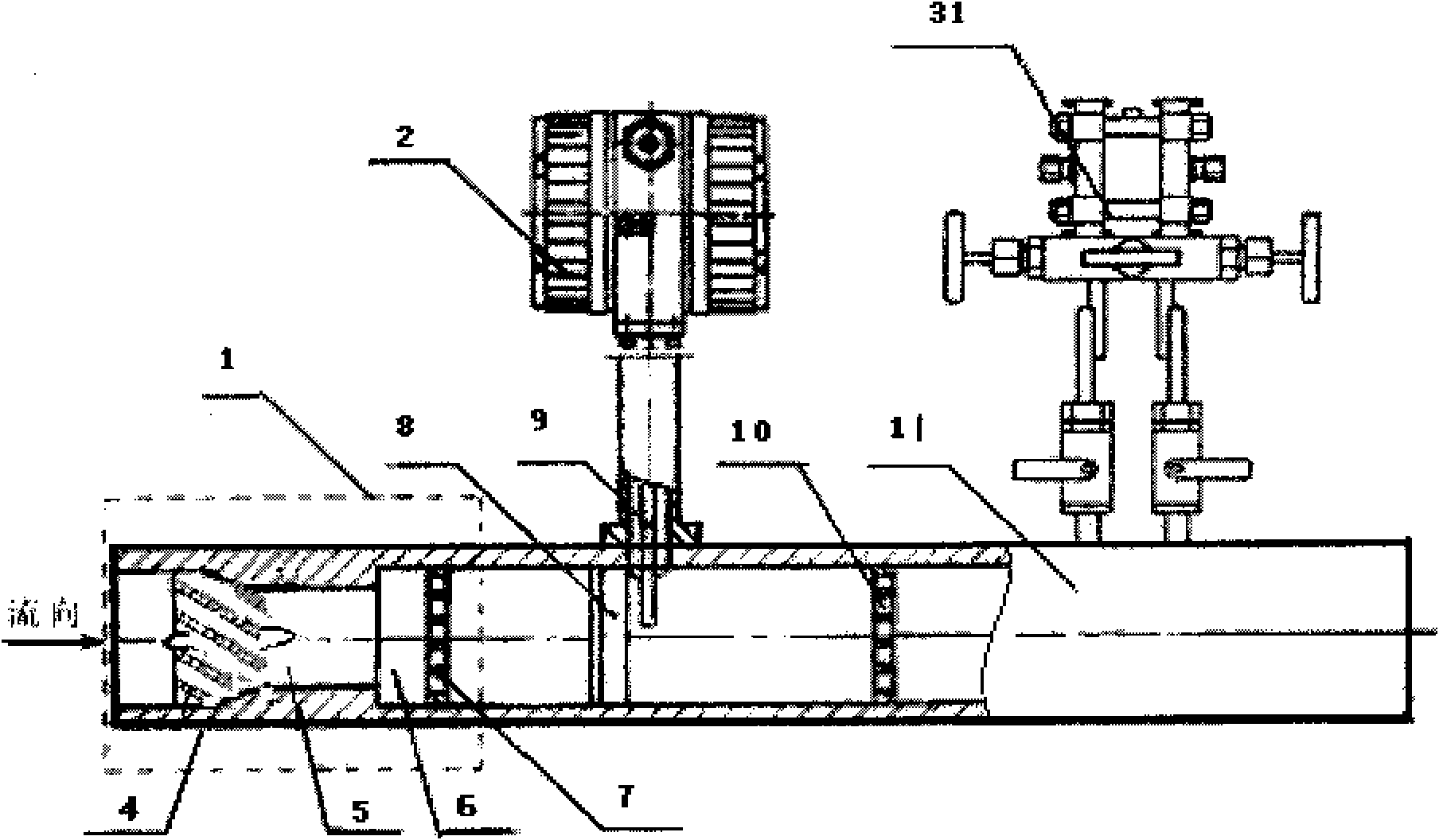
[0020] Example 2: from figure 2 It can be seen from the figure that a composite mass flowmeter includes a pipeline surface body 11, a vortex flow sensor 2, and a differential pressure flow sensor 31. On the pipeline surface body 11, the vortex generating body 8 and the vortex street detection probe 9 are installed in the pipeline surface body 11, a differential pressure flow sensor 31 for measuring flow differential pressure is installed downstream of the pipeline surface body, and a multiphase flow rectifier is installed at the upstream end device 1. Said multi-phase flow rectifying device 1 is the same as that of Embodiment 1. The invention uses a vortex street flow sensor to measure the flow velocity, a differential pressure flow sensor to measure the flow differential pressure, combines the sensing signals, collects, calculates, looks up the table through a microprocessor, and realizes the dryness, density, and flow measurement of the fluid.

Embodiment 3

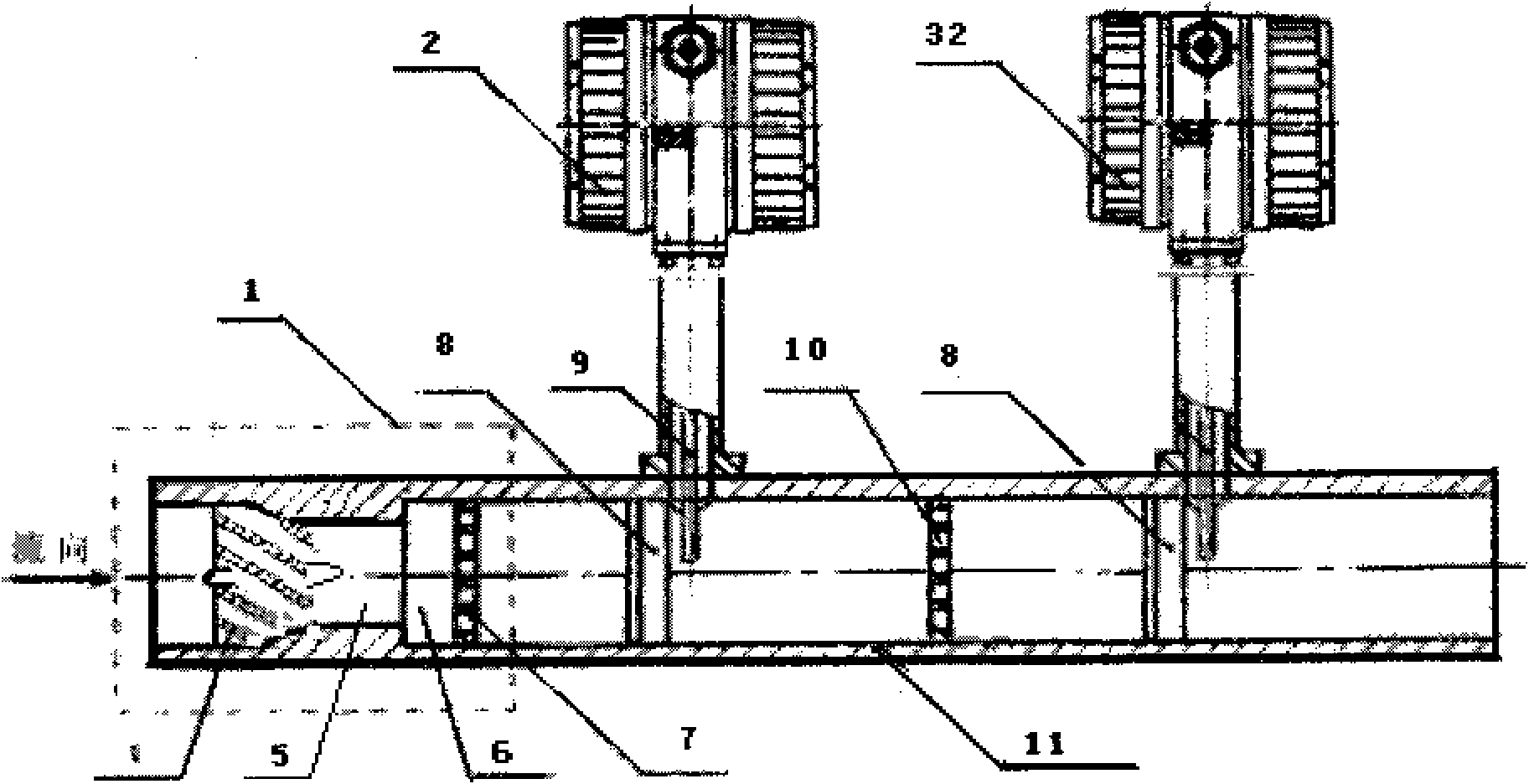
[0021] Example 3: from image 3 It can be seen from the figure that a composite mass flowmeter includes a pipeline surface body 11, a vortex flow sensor 2, and a vortex flow sensor 32. On the surface body 11, the vortex generating body 8 and the vortex detection probe 9 are installed in the pipeline surface body 11, a vortex flow sensor 32 for measuring the vortex lift force is installed downstream of the pipeline surface body, and a multiphase flow rectification device is installed at the upstream end 1. Said multi-phase flow rectifying device 1 is the same as that of Embodiment 1. The present invention utilizes the vortex flow sensor 2 to measure the flow velocity and the vortex flow sensor 32 to measure the vortex lift force, and combines these sensing signals to collect, calculate, and look up the table through the microprocessor to realize the dryness, density, and flow of the fluid. Measurement.

[0022] The invention has the advantages of reasonable structure, conven...


PUM


Abstract

The invention relates to a composite mass flowmeter which comprises a pipeline meter body, a vortex flow sensor, a target flow sensor or a differential pressure flow sensor. The vortex street flow sensor for measuring a flow speed is used as a main body and mounted on the pipeline meter body, the vortex street flow sensor, the target flow sensor for measuring flow speed action force, or the differential pressure flow sensor for measuring flow differential pressure is mounted on the downstream of the pipeline meter body, and a multi-phase flow rectifying device is arranged on the upstream of the pipeline meter body. The invention utilizes the vortex street flow sensor to measure the flow speed, the target flow sensor to measure the flow speed action force or the differential pressure flow sensor to measure the flow differential pressure, and sensor signals are combined and collected, calculated and tabled by a microprocessor to measure the dryness, the density and the flow of fluid. The invention has reasonable structure, simple and convenient mounting and construction and high measurement precision and is particularly suitable for measuring the flow, the dryness and the density of two-phase or multi-phase fluid, thereby being an ideal measuring device for measuring fluid flow in a pipeline.

Description

technical field [0001] The invention relates to a measuring device for fluid flow in a pipeline, in particular to a composite mass flow meter. Background technique [0002] We know that flow measurement is widely used in industrial production and scientific research experiments, such as measuring various flowing media such as liquid, gas, and steam. Flowmeters mainly include vortex flowmeters, target flowmeters, differential pressure flowmeters, etc. [0003] The vortex flowmeter is an oscillating speed flowmeter developed in the 1970s. Its appearance immediately attracted great attention from domestic and foreign flow industries and flow experts, and its development was very rapid. This type of instrument has the characteristics of simple structure, no moving parts, small pressure loss, flow rate has nothing to do with the density and temperature of the medium, and high measurement accuracy. The flowmeter adopts the principle of vortex street (that is, Karman). If a trian...

Claims


Application Information

Patent Timeline
Patent Type & Authority Applications(China)
IPC IPC(8): G01F1/86G01N33/00G01N9/00
Inventor 姚贤卿祁晓明武俊宪朱承纲姚宁
Owner 姚贤卿
Why Eureka
Try Eureka