
Rotor self-radiating system for pump

A self-cooling, rotor technology, applied in the direction of pumps, pump devices, pump components, etc., can solve the problems of easily causing hidden dangers and high water temperature of the pump

Inactive Publication Date: 2018-10-26
浙江东音科技有限公司
View PDF6 Cites 2 Cited by
  • Summary
  • Abstract
  • Description
  • Claims
  • Application Information

AI Technical Summary

Problems solved by technology

Especially in summer, the temperature inside the front cover of the car is high, resulting in high water temperature in the water pump, which is likely to cause hidden dangers

Method used


Image

  • Rotor self-radiating system for pump
  • Rotor self-radiating system for pump

Examples


Embodiment Construction

[0017] In order to make the above objects, features and advantages of the present invention more comprehensible, specific implementations of the present invention will be described in detail below in conjunction with the accompanying drawings. In the following description, numerous specific details are set forth in order to provide a thorough understanding of the present invention.

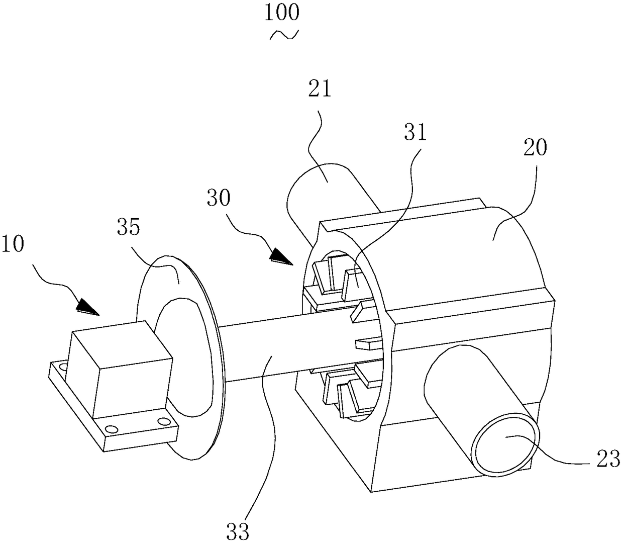
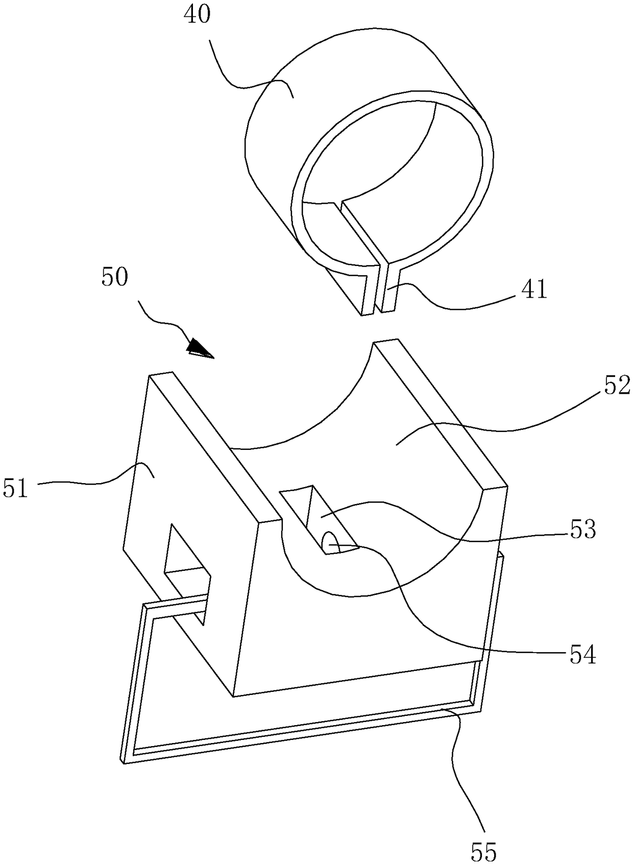
[0018] The invention relates to a pump rotor self-radiating system. For example, the pump rotor self-radiation system includes a driving member, a pump casing and an impeller, the impeller is arranged in the pump casing, and the driving member is connected to the impeller. For example, the impeller includes a wheel body and a plurality of fan blades, one end of the wheel body protrudes from a heat conduction shaft, the plurality of fan blades are arranged around the periphery of the wheel body, and the heat conduction shaft protrudes from the outside the pump casing and connected to the drive. F...


PUM


Abstract

The invention relates to a rotor self-radiating system for a pump. The rotor self-radiating system for a pump comprises a driving part, a pump case and an impeller. The impeller is arranged in the pump case, the driving part is connected to the impeller, the impeller comprises an impeller body and a plurality of fan blades, one end of the impeller body is convexly provided with a heat conduction rotary shaft, the plurality of fan blades are arranged around the periphery of the impeller body, the heat conduction rotary shaft convexly extends outside the pump case and is connected to the drivingpart, a radiating fin is arranged on the end part of the heat conduction rotary shaft, and the radiating fin is aligned with the driving part. The rotor self-radiating system for a pump is better inradiating effect.

Description

technical field [0001] The invention relates to a pump rotor self-radiating system. Background technique [0002] Industrial water pumps, such as automobile water pumps, are generally installed under the front cover of automobiles, which tend to generate a lot of heat in a closed environment. Especially in summer, the temperature inside the front cover of the car is higher, resulting in higher water temperature in the water pump, which is likely to cause hidden dangers. Contents of the invention [0003] Based on this, it is necessary to provide a pump rotor self-radiating system with better heat dissipation effect. [0004] A pump rotor self-radiation system, including a driving part, a pump casing and an impeller, the impeller is arranged in the pump casing, the driving part is connected to the impeller, and the impeller includes a wheel body and a plurality of fan blades One end of the wheel body protrudes from a heat conduction shaft, the plurality of fan blades are ...

Claims


Application Information

Patent Timeline
Patent Type & Authority Applications(China)
IPC IPC(8): F04D29/58F04D13/06H02K9/00H02K5/20H02K5/18
CPCF04D13/06F04D29/5806H02K5/18H02K5/20H02K9/00
Inventor 方秀宝吴刚米勇王恩辉范卫兵
Owner 浙江东音科技有限公司
Learn More