Shield construction machine cutterhead mechanism directly driven by frameless permanent magnet synchronous motor

A technology of permanent magnet synchronous motor and shield machine, applied in synchronous motor with static armature and rotating magnet, magnetic circuit shape/pattern/structure, electromechanical device, etc., can solve the problem of low transmission efficiency, limited escape torque, etc. Solve problems such as low torque, and achieve the effect of reducing equipment weight, improving driving efficiency, and simplifying driving methods

Pending Publication Date: 2018-06-29
HUBEI HUANYEE ELECTROMAGNETIC EQUIP ENG TECH CO LTD
View PDF10 Cites 0 Cited by
  • Summary
  • Abstract
  • Description
  • Claims
  • Application Information

AI Technical Summary

Problems solved by technology

The transmission mechanism is an intermediate device, such as a reduction box, a pulley, etc., and friction pairs are added during work, resulting in low transmission efficiency and high noise
[0004] The driving power source mainly adopts the combination of two-speed motor main drive and hydraulic motor auxiliary drive mode or variable frequency motor drive mode. The above-mentioned two-speed motor main drive and hydraulic motor auxiliary drive mode has the following disadvantages: 1. It cannot continuously adjust the speed ; 2. Poor geological adaptability; 3. High failure rate affects tunneling speed; 4. Hydraulic motor and motor cannot be driven at the same time, etc.
Although the variable-frequency motor drive method can output larger torque at low speeds, it is limited by the maximum electromagnetic torque, and its escape torque is limited.
In fact, we can only increase the motor power to increase the escape torque, which will inevitably lead to a significant increase in the installed power of the variable frequency motor
However, under high-speed tunneling conditions, the motor torque is very small relative to the escape torque, which leads to waste of installed power of the motor

Method used


Image

  • Shield construction machine cutterhead mechanism directly driven by frameless permanent magnet synchronous motor
  • Shield construction machine cutterhead mechanism directly driven by frameless permanent magnet synchronous motor
  • Shield construction machine cutterhead mechanism directly driven by frameless permanent magnet synchronous motor

Examples


Embodiment 1

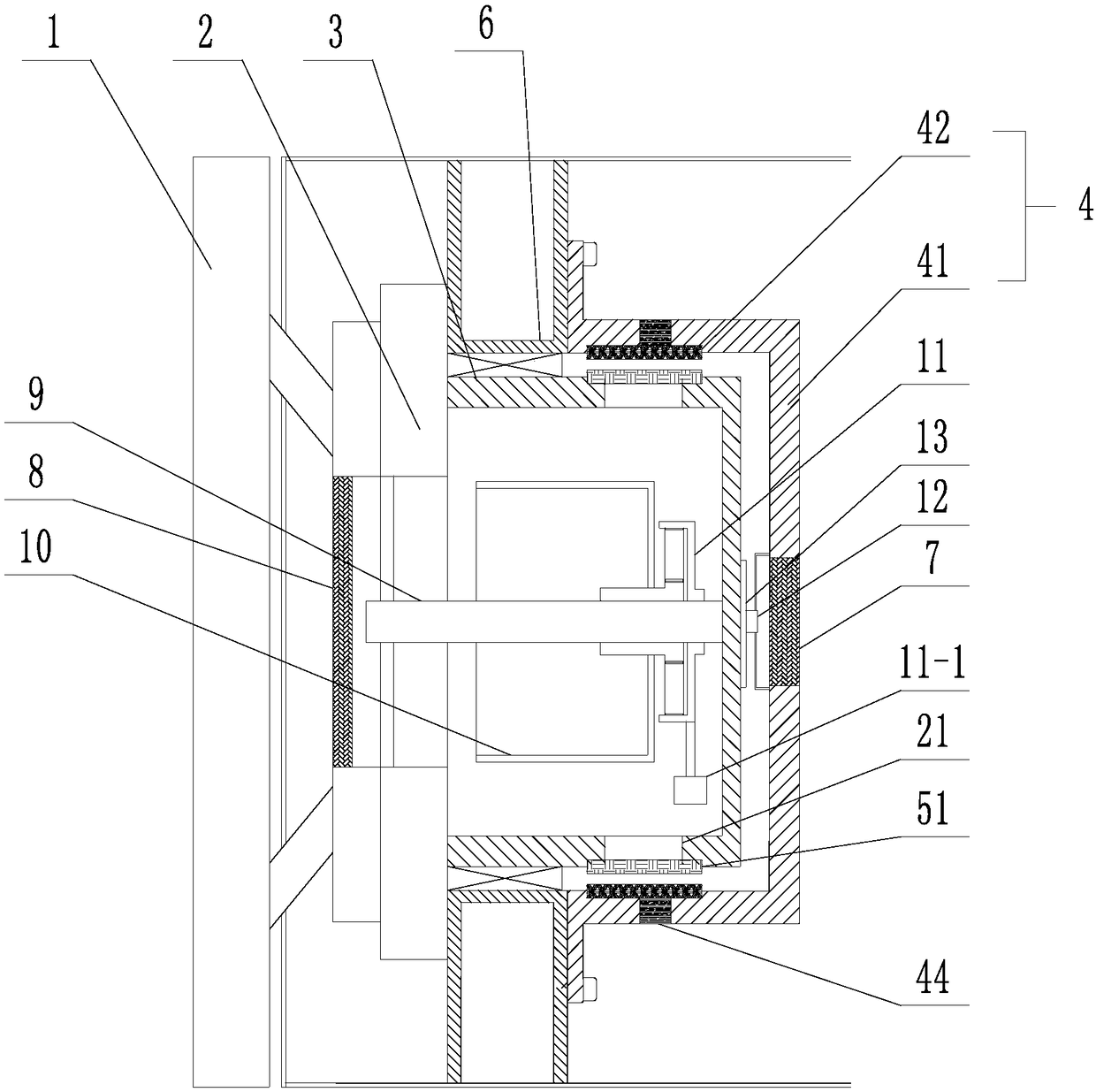
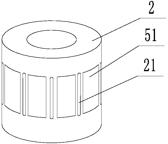
[0031] Such as Figure 1-4 As shown, a shield machine cutter mechanism directly driven by a frameless permanent magnet synchronous motor, the shield machine cutter mechanism includes a cutter head 1, a rotating shaft 2 and a bearing 3, and the cutter head 1 is fixedly installed At one end of the rotating shaft 2; the rotating shaft 2 is fixedly installed in the front body base 6 of the shield machine through a bearing 3; the rotating shaft 2 is directly driven by a frameless permanent magnet synchronous motor, and the frameless The permanent magnet synchronous motor includes a stator assembly 4 and a rotor assembly 5; the stator assembly 4 is fixedly mounted on the body base 6 to provide a rotating magnetic field for the rotor assembly 5; the rotor assembly 5 with permanent magnet properties is fixed installed on the rotating shaft 2;

[0032] Wherein, the stator assembly 4 includes a stator core 1 42 and a stator winding wound on the stator core 1 42, and the stator core 1 4...

Embodiment 2

[0036] Such as Figure 5-8 As shown, a shield machine cutter mechanism directly driven by a frameless permanent magnet synchronous motor, the shield machine cutter mechanism includes a cutter head 1, a rotating shaft 2 and a bearing 3, and the cutter head 1 is fixedly installed At one end of the rotating shaft 2; the rotating shaft 2 is fixedly installed in the front body base 6 of the shield machine through a bearing 3; the rotating shaft 2 is directly driven by a frameless permanent magnet synchronous motor, and the frameless The permanent magnet synchronous motor includes a stator assembly 4 and a rotor assembly 5; the stator assembly 4 is fixedly mounted on the body base 6 to provide a rotating magnetic field for the rotor assembly 5; the rotor assembly 5 with permanent magnet properties is fixed installed on the rotating shaft 2;

[0037] Wherein, the stator assembly 4 includes a second stator core 43 and a stator winding wound on the second stator core 43 , and the seco...

Embodiment 3

[0041] Such as Figure 9 Said, a frameless permanent magnet synchronous motor direct drive shield machine cutter head mechanism, the shield machine cutter head mechanism includes a cutter head 1, a rotating shaft 2 and a bearing 3, the cutter head 1 is fixedly installed At one end of the rotating shaft 2; the rotating shaft 2 is fixedly installed in the front body base 6 of the shield machine through a bearing 3; the rotating shaft 2 is directly driven by a frameless permanent magnet synchronous motor, and the frameless The permanent magnet synchronous motor includes a stator assembly 4 and a rotor assembly 5; the stator assembly 4 is fixedly mounted on the body base 6 to provide a rotating magnetic field for the rotor assembly 5; the rotor assembly 5 with permanent magnet properties is fixed installed on the rotating shaft 2;

[0042] Wherein, the stator assembly 4 includes a stator core 1 42 and a stator core 2 43, the stator core 1 42 and the stator core 2 43 are respectiv...


PUM


Abstract

The invention discloses a shield construction machine cutterhead mechanism directly driven by a frameless permanent magnet synchronous motor. The shield construction machine cutterhead mechanism comprises a cutterhead, a rotation shaft and bearings. The shield construction machine cutterhead mechanism is characterized in that the cutterhead is fixedly arranged at one end of the rotation shaft; therotation shaft is fixedly arranged in a base of a front end body of a shield construction machine through the bearings; the rotation shaft is directly driven by the frameless permanent magnet synchronous motor. The shield construction machine cutterhead mechanism directly driven by the frameless permanent magnet synchronous motor is high in transmission efficiency, low in noise and large in torque.

Description

technical field [0001] The invention belongs to the field of shield machine equipment, in particular to a shield machine cutter head mechanism directly driven by a frameless permanent magnet synchronous motor. Background technique [0002] Shield machine is an important construction machine in shield construction. Because shield construction has the advantages of safety, reliability, low environmental impact, low labor intensity, less earthwork, and high efficiency, it is widely used in urban rail, water conservancy, municipal engineering, mines, highways, Widely used in railway tunnels and other fields. Because the shield machine is often constructed in complex and harsh working environments, its transmission system must be able to withstand heavy loads and large impacts, and is required to have functions such as high power, low speed and high torque output. [0003] Among them, the driving system of the cutter head is the core component of the shield machine, and currentl...

Claims


Application Information

Patent Timeline
Patent Type & Authority Applications(China)
IPC IPC(8): H02K7/14H02K21/12H02K1/12H02K1/28H02K9/06H02K9/22E21D9/08
CPCH02K1/12H02K1/28H02K7/14H02K9/06H02K9/22H02K21/12E21D9/08
Inventor 黄诚杨勇强
Owner HUBEI HUANYEE ELECTROMAGNETIC EQUIP ENG TECH CO LTD
Why Eureka
Try Eureka