Industrial injection molding machine with protection mechanism

A technology of protection mechanism and injection molding machine, which is applied in the field of injection molding machine and can solve the problems of burns, lack of self-cooling function, etc.

Pending Publication Date: 2022-07-12
袁成婕
View PDF1 Cites 0 Cited by
  • Summary
  • Abstract
  • Description
  • Claims
  • Application Information

AI Technical Summary

Problems solved by technology

[0004] However, the technical solution provided by this patent does not have a self-cooling function for the outside of the injection molding base. When the injection head injects the raw material into the mold, the heat is easily transferred to the outside of the injection molding base. If the heat cannot be cooled and dissipated in time, the injection molding personnel There is a safety hazard of being scalded when accidentally touching the injection molding base

Method used


Image

  • Industrial injection molding machine with protection mechanism
  • Industrial injection molding machine with protection mechanism
  • Industrial injection molding machine with protection mechanism

Examples


Embodiment 1

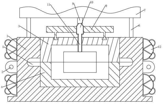
[0039] see Figure 1-2 and Figure 8 , in the embodiment of the present invention, an industrial injection molding machine with a protection mechanism, comprising:

[0040] The injection molding base 1, the middle end of the left and right sides of the injection molding base 1 is fixedly installed with the fixed seat 2, the upper mold 3 and the lower mold 4 are fixedly installed on the inner upper and lower ends of the injection molding base 1, and the upper mold 3 and the lower mold 4 are fixedly installed. The outer surfaces of the left and right sides are fixedly installed with the parting ear seats 5, the left and right ends of the top side outer surface of the injection molding base 1 are fixedly installed with support columns 6, and the top positions of the support columns 6 are fixedly installed with the injection molding machine main body 7. The injection molding machine main body The injection head 8 is fixedly installed through the central position of the bottom end...

Embodiment 2

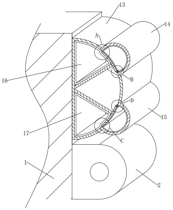
[0054] see Figure 2-4 and Figure 7 , compared with Embodiment 1, the difference between the embodiment of the present invention is that the upper fixing plate 18 is fixed and installed obliquely at the upper end of the left inner wall of the main shell 13, and the angle between the upper fixing plate 18 and the upper and lower vertical planes is 59°;

[0055] The upper fixing plate 18 here is for the convenience of limiting and supporting the upper main air bag 19 together with the inner wall of the main casing 13 , so that the upper main air bag 19 can smoothly expand into the upper auxiliary casing 14 after being heated and expanded.

[0056] In the embodiment of the present invention, the upper main air bag 19 is embedded between the top side outer surface of the upper fixing plate 18 and the upper end surface of the inner wall of the main shell 13 , and the upper main air bag 19 is in the shape of a fan with an inner angle of 59° and an upper right outer convex. ;

[...

Embodiment 3

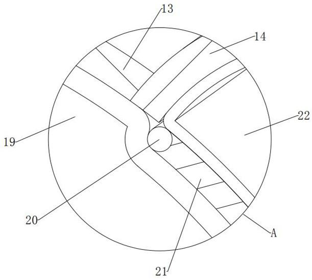
[0064] see figure 2 and Figure 5-7 , with respect to Embodiment 1, the embodiment of the present invention differs in that the lower end position of the left inner wall of the main shell 13 is obliquely fixed and installed with a lower fixing plate 24, and the angle between the lower fixing plate 24 and the horizontal plane is 31°;

[0065] The lower fixing plate 24 here is for the convenience of limiting and supporting the lower main air bag 25 together with the inner wall of the main casing 13 , so that the lower main air bag 25 can smoothly expand into the lower auxiliary casing 15 after being heated and expanded.

[0066] In the embodiment of the present invention, a lower main air bag 25 is embedded between the outer surface of the bottom side of the lower fixing plate 24 and the lower end surface of the inner wall of the main casing 13 , and the lower main air bag 25 is in the shape of a fan with an inner angle of 59° and a lower right outer convex. shape;

[0067] The...


PUM


Abstract

The invention provides an industrial injection molding machine with a protection mechanism, which comprises: a plurality of self-cooling assemblies, which can automatically cool at high temperature, are fixedly mounted at the upper and lower ends of the outer surfaces of the left and right sides of an injection molding base in equal adjacent rows; the self-cooling assembly comprises a main shell, an upper auxiliary shell, a lower auxiliary shell, an upper discharging assembly and a lower discharging assembly, wherein the upper discharging assembly can guide out one kind of cooling materials at the high temperature, and the lower discharging assembly can guide out the other kind of cooling materials at the high temperature. A plurality of main shells are adjacently and fixedly mounted at the upper and lower ends of the outer surfaces of the left and right sides of the injection molding base; an upper auxiliary shell is fixedly installed in the upper through groove in a penetrating mode. According to the industrial injection molding machine with the protection mechanism, the outer side of the injection molding base can have a self-cooling function, when an injection molding head injects raw materials in a mold, even if heat is transferred out of the injection molding base, the heat can be timely cooled and dissipated, and the potential safety hazard that injection molding personnel are scalded when accidentally making contact with the injection molding base is eliminated.

Description

technical field [0001] The invention relates to the technical field of injection molding machine injection molding, more particularly, to an industrial injection molding machine with a protection mechanism. Background technique [0002] The existing injection molding machine usually injects and extrudes the injection material into the cavity under the action of pressure. During the injection molding process, a large pressure is applied to the injection material. When the injection molding is completed, in order to ensure uniform filling of the injection molding, usually Excessive injection molding is used, which is very easy to cause the injection material to overflow under the action of pressure, and pressurize and compress the material. When the closing pressure of the injection head disappears, the high-temperature injection material will splash or flow back, thereby contaminating the injection head and increasing the size of the injection. The dangers of injection moldin...

Claims


Application Information

Patent Timeline
Patent Type & Authority Applications(China)
IPC IPC(8): B29C45/84B29C45/72
CPCB29C45/84B29C45/72
Inventor 袁成婕
Owner 袁成婕
Why Eureka
Try Eureka