
Spun yarn drying box

A drying box and spinning technology, used in drying, dryers, progressive dryers, etc., can solve the problems of troublesome cloth installation, uneven heating of heated cloth, slow drying rate, etc., and improve the installation rate. , the effect of reducing time and labor intensity

Inactive Publication Date: 2018-10-26
柳州大蘑王网络科技有限公司
View PDF0 Cites 4 Cited by
  • Summary
  • Abstract
  • Description
  • Claims
  • Application Information

AI Technical Summary

Problems solved by technology

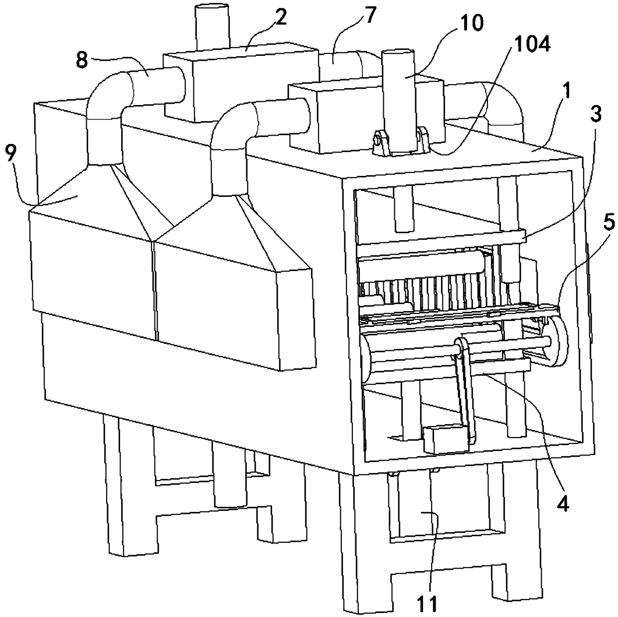
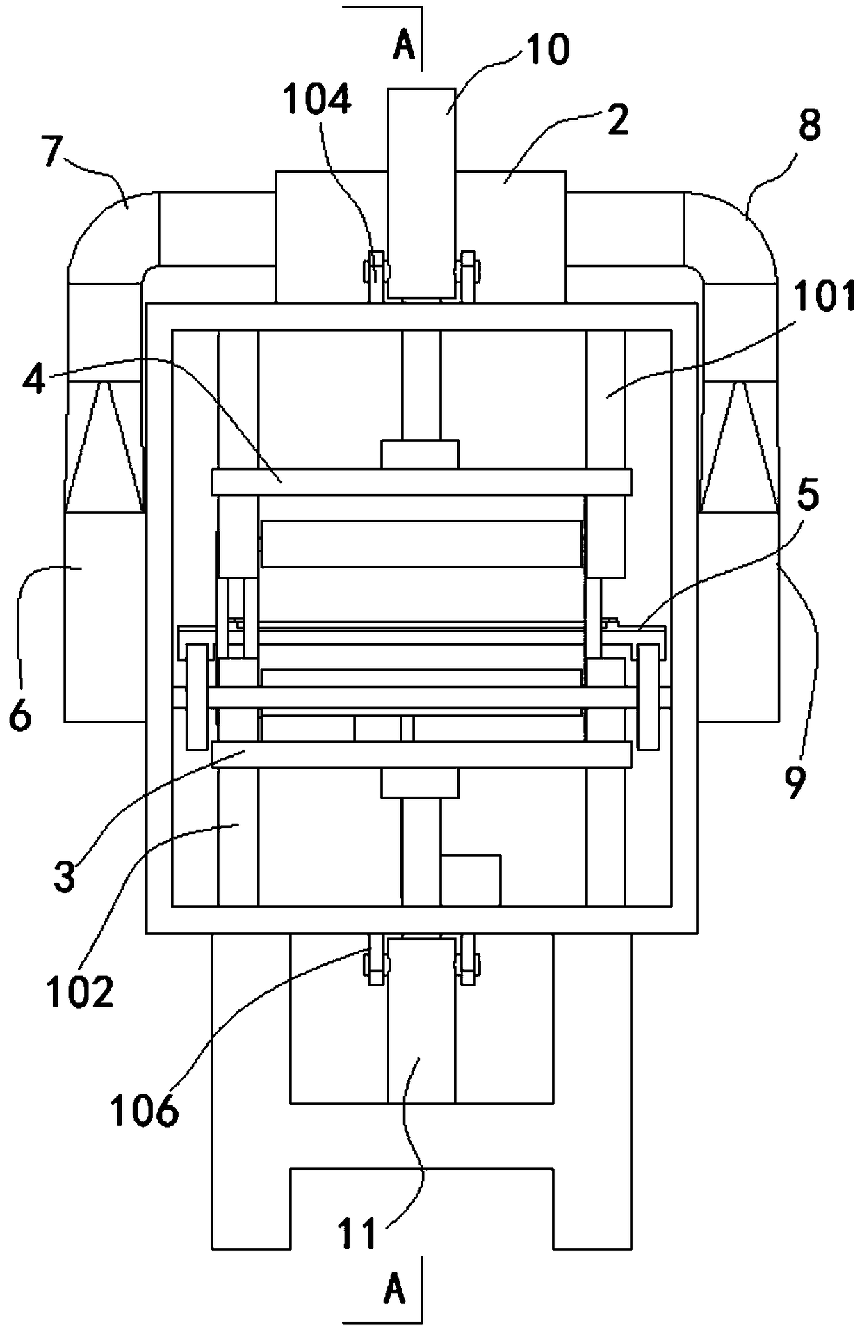
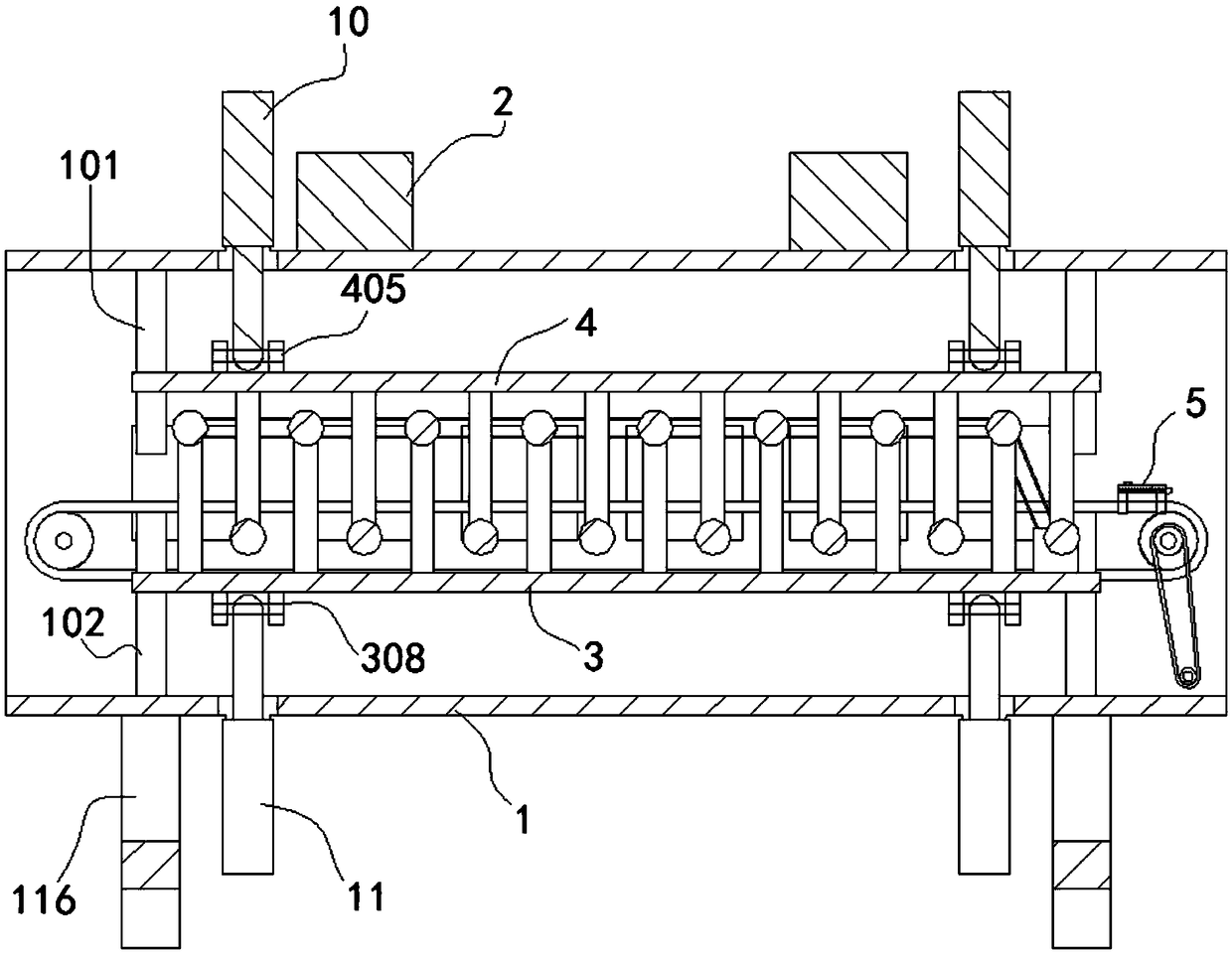
[0004] The object of the present invention is to provide a spinning drying box, through the designed box body, heater, active conveying assembly, driven conveying assembly, clamping conveying assembly, wind collecting box, first pipeline and second pipeline, to realize heating The external device heats the air circulation in the box, which is convenient for the reciprocating and staggered conveying of the cloth, and the five wrinkles are conveyed by the roller, and the cloth is pulled and installed, which solves the problem of uneven heating of the cloth with the built-in heating device of the existing heating device, slow drying speed, and troublesome installation of the cloth The problem

Method used


Image

  • Spun yarn drying box
  • Spun yarn drying box
  • Spun yarn drying box

Examples


Embodiment Construction

[0030] The following will clearly and completely describe the technical solutions in the embodiments of the present invention with reference to the accompanying drawings in the embodiments of the present invention. Obviously, the described embodiments are only some, not all, embodiments of the present invention. Based on the embodiments of the present invention, all other embodiments obtained by persons of ordinary skill in the art without creative efforts fall within the protection scope of the present invention.

[0031] see Figure 1-5 As shown, the present invention is a spinning drying box, which includes a box body 1, the first guide column 101 is fixed in a rectangular arrangement on the inner wall of the box body 1; the side of the first guide column 101 is slidably fitted with a driven conveying assembly 4; The other inner wall of the box body 1 is fixed in a rectangular arrangement with a second guide column 102; the side of the second guide column 102 is slidably fi...


PUM


Abstract

The invention discloses a spun yarn drying box and relates to the technical field of textile equipment. The spun yarn drying box comprises a box body. First guiding columns are fixed to one inner wallof the box body in a rectangular arrangement mode, and the peripheral side faces of the first guiding columns are in sliding fit with a driven conveying assembly; second guiding columns are fixed tothe other inner wall of the box body in a rectangular arrangement mode, and the peripheral side faces of the second guiding columns are in sliding fit with a driving conveying assembly; a plurality offirst through holes are formed in one surface of the box body, and a plurality of second through holes are formed in the other surface of the box body; and a plurality of first double-lug seats are fixed to one surface of the box body. According to the spun yarn drying box, by designing the box body, a heater, the driving conveying assembly, the driven conveying assembly, a clamping conveying assembly and a wind collecting box, the heater is externally arranged to circularly heat air in the box body; and cloths are conveyed conveniently in reciprocating and staggered mode, wrinkle marks are avoided through roller conveying, the cloths are mounted in a pulling mode, and the problems that an existing heating device is internally arranged to heat the cloths, consequently, the cloths are heated unevenly, the drying rate is low, and cloth mounting is troublesome are solved.

Description

technical field [0001] The invention belongs to the technical field of textile equipment, in particular to a spinning drying box. Background technique [0002] The drying oven is used for polymer material drying, resin curing, pharmaceuticals, paint baking, electronics, electroplating, pharmaceuticals, printing baking, motor drying, transformer drying, industrial heat treatment, disinfection, heating, heat preservation and other processes in factories and scientific research units equipment. According to the performance, the drying box can be divided into spinnable drying box, precision drying box, nitrogen-filled drying box, vacuum drying box, explosion-proof drying box, electric blast drying box, hot air circulation drying box, etc. In the production of textiles, the dryer is one of the indispensable production equipment. The quality of the dryer will directly affect the quality of the textile. The existing dryers mainly include a drying box and a drying box. The heating...

Claims


Application Information

Patent Timeline
Patent Type & Authority Applications(China)
IPC IPC(8): F26B13/14F26B21/00F26B21/04F26B25/00F26B25/20
CPCF26B13/14F26B21/001F26B21/004F26B21/04F26B25/003F26B25/20
Inventor 杨继华李振聪
Owner 柳州大蘑王网络科技有限公司
Learn More