
White light interference signal background light intensity real-time separation method

A technology of white light interference and background light intensity, which is applied in the field of real-time separation of white light interference signal and background light intensity, and can solve the problems of no longer applicable, increase of white light interference signal calculation method error, measurement time aggravating environmental scattering and light source instability.

Active Publication Date: 2018-10-26
CIVIL AVIATION UNIV OF CHINA
View PDF6 Cites 1 Cited by
  • Summary
  • Abstract
  • Description
  • Claims
  • Application Information

AI Technical Summary

Problems solved by technology

However, when measuring the surface of mechanical parts, the vertical measurement range often reaches more than a dozen or tens of microns, and the prolongation of the measurement time intensifies the influence of environmental scattering and unstable light sources.
At the same time, due to the larger surface roughness, the surface diffuse reflection is more serious
In this case, the background light intensity of the extracted white light interference signal is no longer a theoretical constant value, but presents a nonlinear intensity change. As a result, the original background extraction method becomes inapplicable. This also increases the possibility of error in the white light interference signal solution method

Method used


Image

  • White light interference signal background light intensity real-time separation method
  • White light interference signal background light intensity real-time separation method
  • White light interference signal background light intensity real-time separation method

Examples


Embodiment Construction

[0039] The real-time separation method of the background light intensity of the white light interference signal provided by the method operates in units of pixels, and the separation method of the background light intensity is the same for other pixels in the image. The method for real-time separation of the background light intensity of the white light interference signal provided by the present invention will be described in detail below in conjunction with the accompanying drawings and specific embodiments, and a specific pixel point is taken as an example in the description.

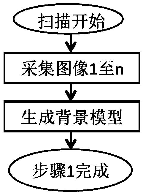
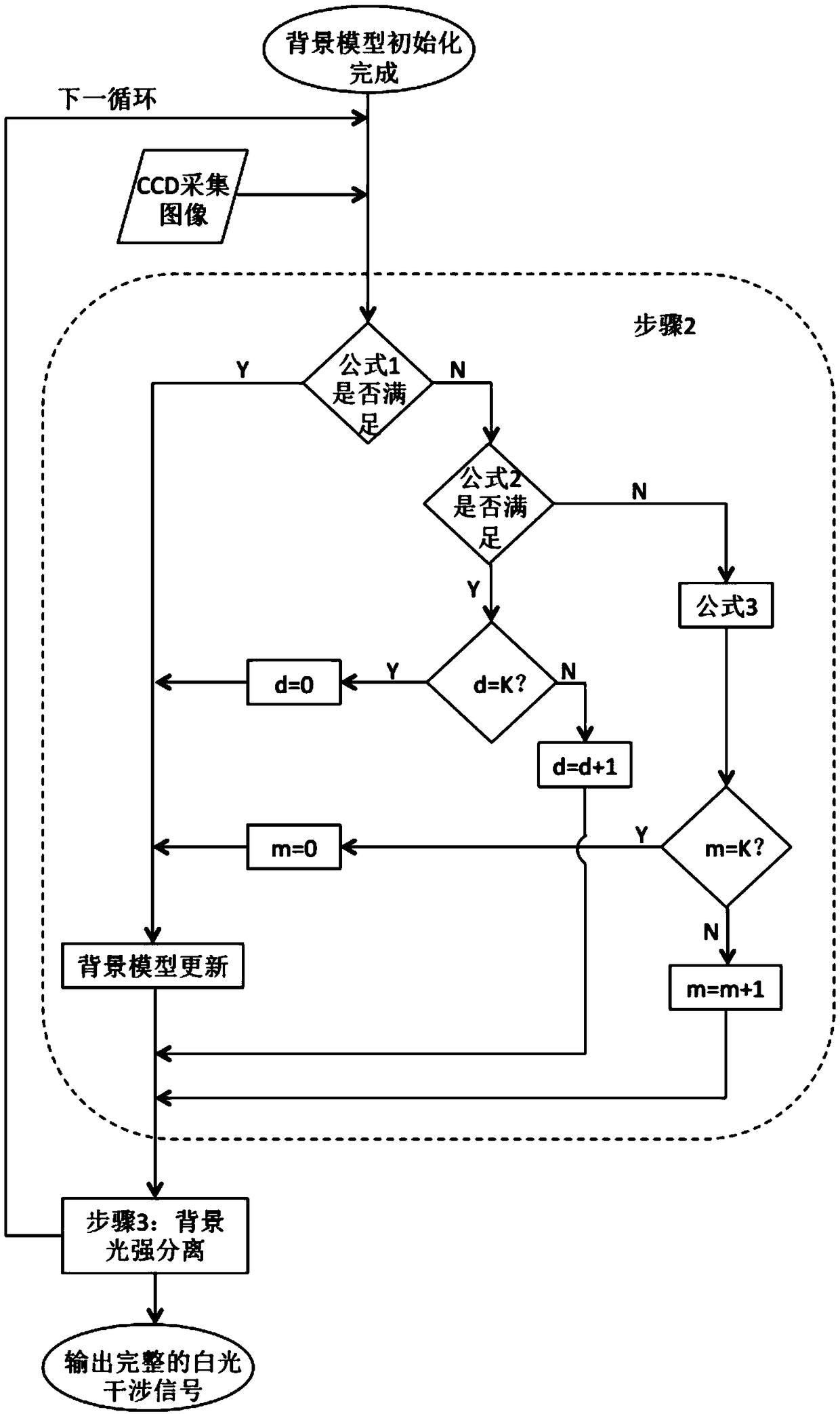
[0040] like figure 1 , figure 2 As shown, the white light interference signal background light intensity real-time separation method provided by the present invention includes the following steps in order:

[0041] Step 1: After the scanning starts, use the CCD camera to record the images at the first n scanning positions, so as to obtain the light intensity change of a specific pixel point in the ...


PUM


Abstract

The invention discloses a white light interference signal background light intensity real-time separation method. The method includes, after scanning begins, utilizing a CCD camera to record images ofn scanning positions to obtain light intensity change conditions of a specific pixel point in the images, and generating a set of background point sets for the pixel point; starting from the n+1th scanning positions, each frame image being collected by the CCD camera, for the n+1th scanning positions, judging whether update needs to be performed on an initial background model by the light intensity value and the initial background model of the pixel point after the initial background model of the pixel point is established; for the current scanning position after the n+1th scanning positions,judging whether the update and other steps need to be performed on a current background model according to the light intensity value and the current background model of the pixel point; and separating background light intensity according to the updated current background model, and extracting white light interference signals in real time. The method can effectively distinguish the background light intensity and the white light interference signals and meet real-time requirements, and is simple in calculating processes.

Description

technical field [0001] The invention belongs to the technical field of optical precision non-destructive testing, in particular to a method for real-time separation of background light intensity of white light interference signals. Background technique [0002] Optical precision non-destructive testing technology, as an important part of ultra-precision testing technology, has developed rapidly in recent years, and has huge application requirements in aerospace, automobile manufacturing, medical health, energy industry, and national defense security. , Measurement accuracy and application fields have made great progress. In this context, the demand for optical precision non-destructive testing in the industry is becoming more and more specific, often based on certain specific measurement objects, which also promotes the research work in this field to a more refined direction develop. [0003] As an important branch of optical nondestructive testing technology, white light ...

Claims


Application Information

Patent Timeline
Patent Type & Authority Applications(China)
IPC IPC(8): G01B9/02
CPCG01B9/02048G01B9/0209
Inventor 马龙裴昕孙凤鸣
Owner CIVIL AVIATION UNIV OF CHINA
Learn More