A double-coil charging coil and its manufacturing method

A technology for charging coils and manufacturing methods, which is applied in coil manufacturing, inductance/transformer/magnet manufacturing, transformer/inductor coil/winding/connection, etc., and can solve problems such as large resistance

Active Publication Date: 2019-06-11
DONGGUAN LINGYI PRECISION MFG TECH CO LTD
View PDF6 Cites 0 Cited by
  • Summary
  • Abstract
  • Description
  • Claims
  • Application Information

AI Technical Summary

Problems solved by technology

However, this method still has shortcomings, that is, during the flow of the adhesive, because the adhesive has a certain viscosity, the resistance is very large, and it is easy to drive the coil. Due to the first distance between the coils and the second The distance itself is very small. After fitting each other, the distance between the first stamped coil and the second stamped coil is actually very small. During the process of displacement of the adhesive, it is easy to separate the first stamped coil and the second stamped coil. The stamped coils squeeze together, creating a short circuit

Method used


Image

  • A double-coil charging coil and its manufacturing method
  • A double-coil charging coil and its manufacturing method
  • A double-coil charging coil and its manufacturing method

Examples


Embodiment Construction

[0054] Attached below Figures 1 to 12 The present invention is described in further detail.

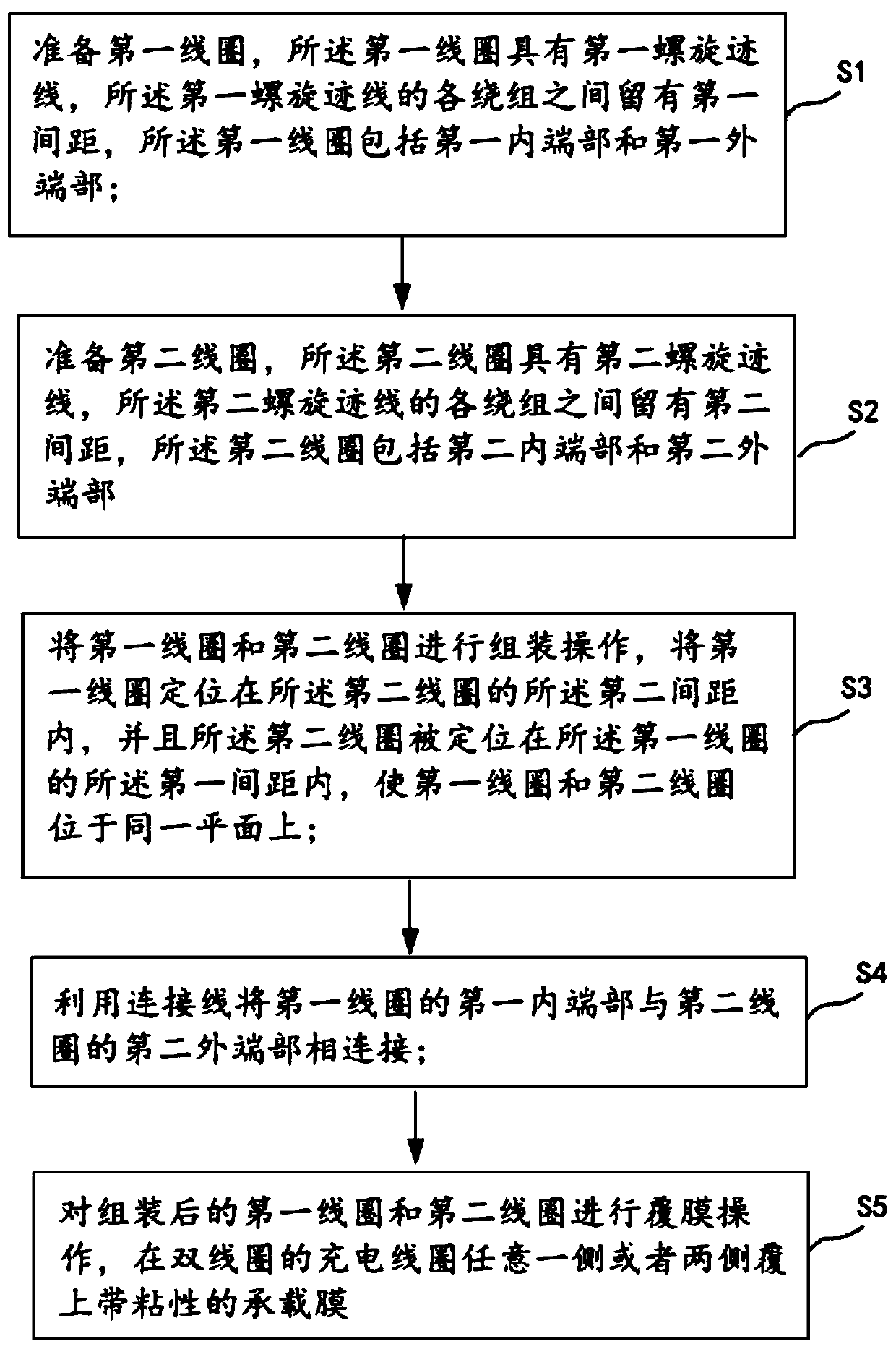
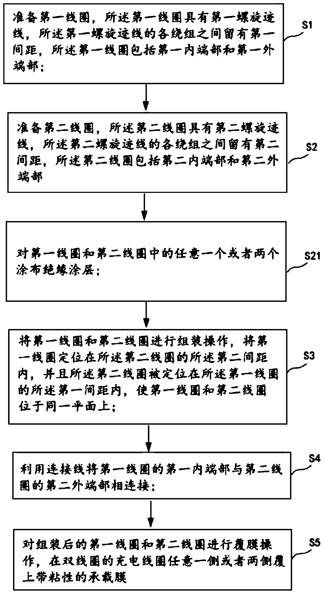
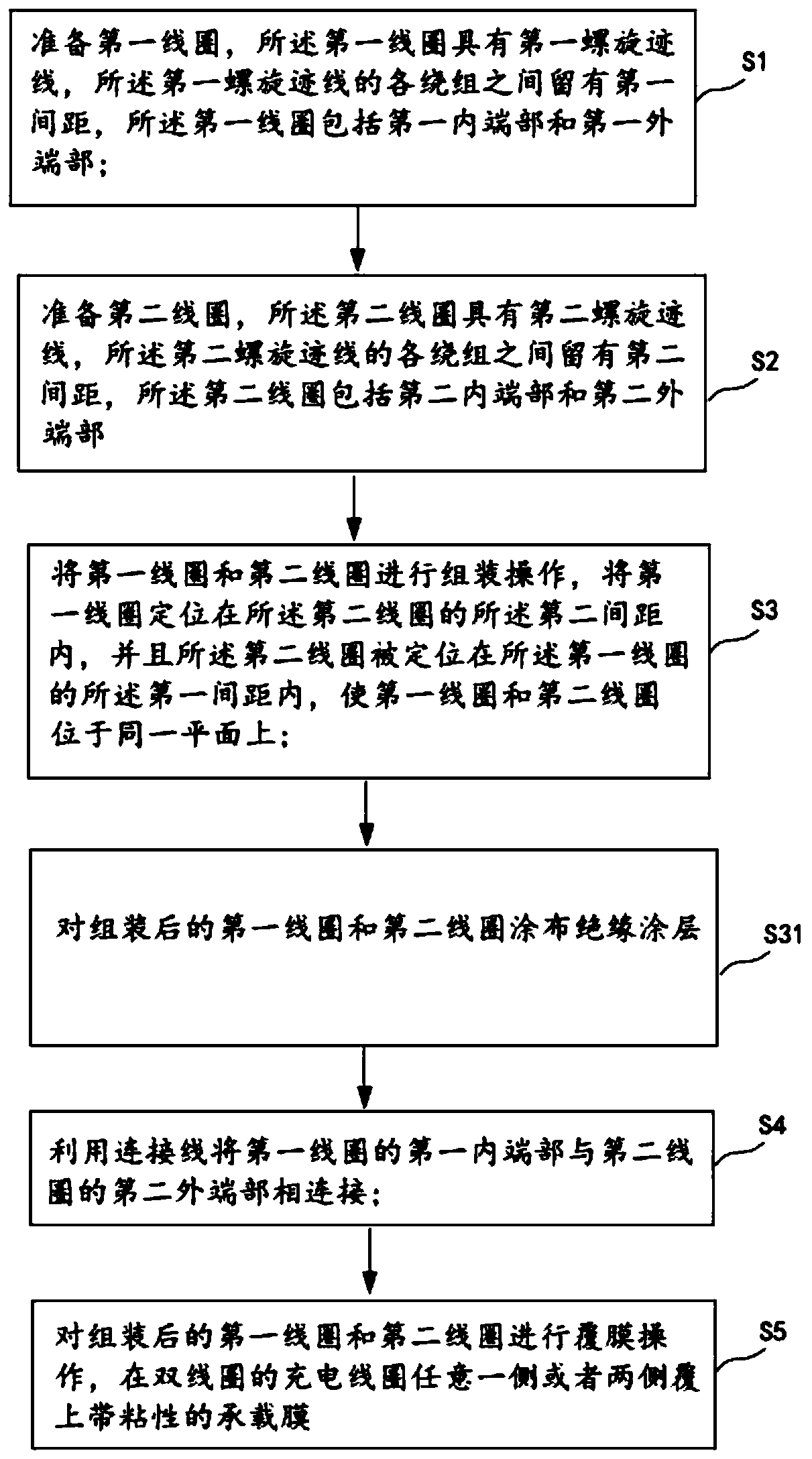
[0055] According to one aspect of the present invention, a method for manufacturing a double-coil charging coil is provided, such as figure 1 As shown, it includes the following steps;

[0056] Step S1: Prepare a first coil 1, the first coil 1 has a first helical trace 2, a first spacing 3 is left between the windings of the first helical trace 2, the first coil 1 comprises a first inner end 4 and the first outer end portion 5;

[0057] Step S2: Prepare the second coil 6, the second coil 6 has a second helical trace 7, a second spacing 8 is left between the windings of the second helical trace 7, the second coil 6 includes a second inner end 9 and the second outer end portion 10;

[0058] Step S3: The first coil 1 and the second coil 6 are assembled, the first coil 1 is positioned within the second interval 8 of the second coil 6 , and the second coil 6 is positioned within the f...


PUM


Abstract

Disclosed in the present invention are a charging coil having double coils, and a manufacturing method therefor. The method comprises the following steps: preparing a first coil, the first coil having a first spiral trace, windings of the first spiral trace being spaced by a first spacing, and the first coil comprising a first inner end and a first outer end; preparing a second coil, the second coil having a second spiral trace, windings of the second spiral trace being spaced by a second spacing, and the second coil comprising a second inner end and a second outer end; assembling the first coil and the second coil, positioning the first coil within the second spacing of the second coil, and positioning the second coil within the first spacing of the first coil, so that the first coil and the second coil are located in the same plane; and connecting the first inner end of the first coil to the second outer end of the second coil by a connecting wire. The beneficial effects are that the charging coil can maintain a very small thickness, and thus can be applied in the limited internal space of a mobile phone, and a higher charging efficiency is provided.

Description

technical field [0001] The invention relates to the field of manufacturing charging coils, in particular to a method for manufacturing a double-coil charging coil. Background technique [0002] The existing coil processing adopts copper wire winding method, which has poor dimensional accuracy, low charging efficiency, and poor heat dissipation effect, which cannot meet the technical requirements of wireless charging coils. [0003] There are also some new manufacturing methods for wireless charging coils. For example, the Chinese invention patent with publication number CN104465067A discloses a manufacturing method for wireless charging coils, including the following steps: 1) preparing plastic parts; preparing laser-activatable coatings ; 2) Spray a layer of laser-activatable paint on the front and back of the plastic part to be treated; 3) Use a laser to laser out the spiral coil groove and the feed point groove on the front of the plastic part, and the inner terminal and ...

Claims


Application Information

Patent Timeline
Patent Type & Authority Patents(China)
IPC IPC(8): H01F27/28H01F38/14H01F41/04H01F41/12H02J50/10
CPCH01F27/2823H01F38/14H01F41/04H01F41/127H02J50/10
Inventor 梁平平
Owner DONGGUAN LINGYI PRECISION MFG TECH CO LTD
Why Eureka
Try Eureka