
Optical sensing system, optical sensing component and manufacturing method thereof

A technology of optical sensing and optical sensing components, which is applied in radio wave measurement systems, electrical components, measuring devices, etc., and can solve problems such as increased component costs, increased volume, and misjudgment of distances from objects 110

Pending Publication Date: 2018-10-26
NANJING SILERGY SEMICON TECH CO LTD
View PDF0 Cites 4 Cited by
  • Summary
  • Abstract
  • Description
  • Claims
  • Application Information

AI Technical Summary

Problems solved by technology

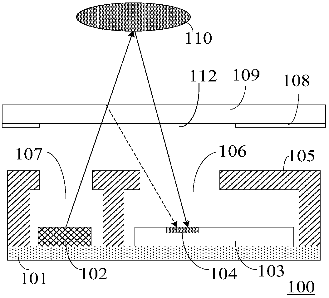
However, the surface of the transparent cover layer 109 will cause reflection of light between media of different refractive index, as shown by the dotted line in the figure
The surface reflected light can also reach the photo-sensing element 104 through the receiving opening 112, thereby generating optical crosstalk, thereby causing misjudgment of the distance of the object 110
[0005] In the further improved optical sensing components, the optical crosstalk is reduced by increasing the distance between the light-emitting element and the light-sensing chip. increase

Method used


Image

  • Optical sensing system, optical sensing component and manufacturing method thereof
  • Optical sensing system, optical sensing component and manufacturing method thereof
  • Optical sensing system, optical sensing component and manufacturing method thereof

Examples


Embodiment Construction

[0060] Hereinafter, the present invention will be described in more detail with reference to the accompanying drawings. In the various figures, identical elements are indicated with similar reference numerals. For the sake of clarity, various parts in the drawings have not been drawn to scale. Also, some well-known parts may not be shown. For the sake of simplicity, the semiconductor structure obtained after several steps can be described in one figure.

[0061] It should be understood that when describing the structure of a device, when a layer or a region is referred to as being "on" or "over" another layer or another region, it may mean being directly on another layer or another region, or Other layers or regions are also included between it and another layer or another region. And, if the device is turned over, the layer, one region, will be "below" or "beneath" the other layer, another region.

[0062] If it is to describe the situation directly on another layer or an...


PUM


Abstract

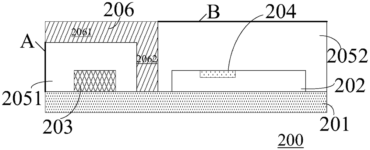
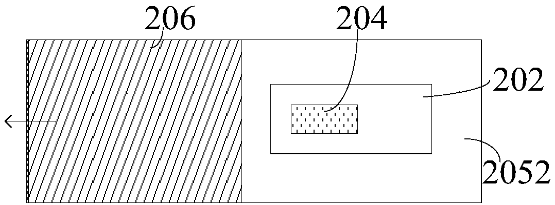
The invention discloses an optical sensing system, an optical sensing component and a manufacturing method thereof. The optical sensing component comprises a light-emitting element; a first structuralbody packaging the light-emitting element, wherein the surface of the first structural body is provided with a light emergent surface; a light sensing element; and a second structural body packagingthe light sensing element, wherein the surface of the second structural body is provided with a light receiving surface. The light emitted by the light-emitting element is emitted outside the opticalsensing component through the light emergent surface and then reflected by the object to be measured. The reflected light reflected by the object to be measured reaches the light sensing element through the light receiving surface. The light sensing element senses the distance of the object to be measured according to the received reflected light, wherein the light emergent surface is not parallelto the light receiving surface. The light emergent surface and the light receiving surface of the optical sensing component are arranged on different planes so that the optical crosstalk can be reduced and the accuracy of distance detection can be enhanced.

Description

technical field [0001] The present invention relates to the technical field of semiconductor devices, and more particularly, to an optical sensing system, an optical sensing component and a manufacturing method thereof. Background technique [0002] Proximity detection is a technology that detects the proximity of objects under non-contact conditions. It has a wide range of applications in industrial automatic control, Internet of Things technology, electronic games and other fields. According to different detection principles, different similar sensors including capacitive, inductive and photoelectric can be used for proximity detection. The working principle of the photoelectric sensor is to irradiate the object with the light emitted by the light source, and after being reflected by the object, the photoelectric sensor receives the light energy and converts it into an electrical signal. The detection distance of the photoelectric sensor is suitable for various everyday a...

Claims


Application Information

Patent Timeline
IPC IPC(8): H01L25/16H01L31/16H01L31/18G01S17/04
CPCH01L25/167H01L31/16H01L31/18G01S17/08G01S17/04G01S7/4813
Inventor 林苏逸
Owner NANJING SILERGY SEMICON TECH CO LTD
Learn More