Welding method of steel pipe and joint of steel pipe structure

A welding method and technology for steel pipes, applied in welding equipment, welding equipment, auxiliary welding equipment, etc., can solve problems such as improper position relationship between steel pipes and joints

Active Publication Date: 2020-05-15
HITACHI ZOSEN CORP
View PDF9 Cites 0 Cited by
  • Summary
  • Abstract
  • Description
  • Claims
  • Application Information

AI Technical Summary

Problems solved by technology

As a result, in the case of a large manufacturing error of the steel pipe, the problem arises that the positional relationship between the welded steel pipe and the joint is inappropriate.

Method used


Image

  • Welding method of steel pipe and joint of steel pipe structure
  • Welding method of steel pipe and joint of steel pipe structure
  • Welding method of steel pipe and joint of steel pipe structure

Examples


Embodiment Construction

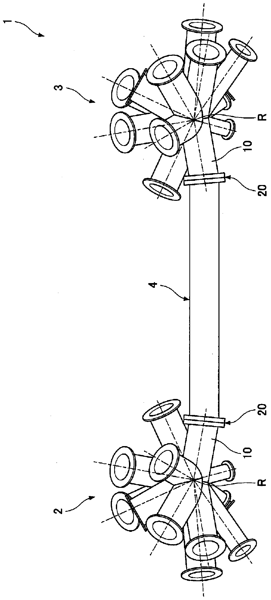
[0020] Hereinafter, the method of welding the steel pipe and the joint of the steel pipe structure according to the embodiment of the present invention will be described. Such as figure 1 As shown, the purpose of welding the steel pipes and joints of the steel pipe structure is to manufacture the connected steel pipe structure 1, and the connected steel pipe structure 1 is made by combining multiple ( figure 1 Two steel pipe structures 2 and 3 are formed by connecting steel pipe structures 2 and 3 different from these steel pipe structures 2 and 3 (hereinafter referred to as steel pipes 4 for connection).

[0021] First, the outline of the above-mentioned connected steel pipe structure 1 will be described with reference to the drawings.

[0022] Such as figure 1 As shown, the connecting steel pipe structure 1 has: a plurality of ( figure 1 As an example, two) steel pipe structures 2, 3; a connecting steel pipe 4 connecting these steel pipe structures 2, 3;

[0023] The abo...


PUM


Abstract

The invention provides a welding method for a steel pipe (10) and a joint (20) of a steel pipe structure. The welding method includes: a measurement process of measuring the manufacturing error of the steel pipe (10); a calculation process of calculating the positions of the steel pipe (10) and the joint (20) that absorb the manufacturing error measured in the measurement process; and a welding process , welding the steel pipe (10) and the joint (20) at the positions of the steel pipe (10) and the joint (20) calculated in the calculation step.

Description

technical field [0001] The invention relates to a welding method for a steel pipe and a joint of a steel pipe structure. Background technique [0002] By joining steel pipes with joints, it is possible to form a length longer than a single steel pipe. By joining such joints, the steel pipes are usually aligned in a straight line. However, depending on the installation site where the steel pipes are installed, it may be desirable not to join the steel pipes in a straight line, but to join the steel pipes with a slight bend. Therefore, a linker suitable for such use is also disclosed (for example, refer to Patent Document 1). The joint described in the above-mentioned Patent Document 1 further receives the pipe end obliquely installed at a certain angle on the outer periphery of the end portion of the steel pipe (pipe) at the above-mentioned angle. [0003] Patent Document 1: Japanese Utility Model Publication No. 46-35481 [0004] However, with the joint described in Pate...

Claims


Application Information

Patent Timeline
Patent Type & Authority Patents(China)
IPC IPC(8): B23K37/053B23K9/028
CPCB23K37/053B23K31/02B23K31/12B23K2103/04B23K2101/06B23K2101/10G01B21/00G01B21/20B23K9/0282B23K31/027
Inventor 山田顺也中谷光良谷和彦成山达也汤藤尚人
Owner HITACHI ZOSEN CORP
Why Eureka
Try Eureka