Seal-equipped bearing, and ball bearing

A technology with seals and ball bearings, applied in the direction of ball bearings, rotating bearings, bearings, etc., can solve problems such as difficult management, and achieve the effect of suppressing temperature rise, increasing speed, and reducing sealing torque

Active Publication Date: 2018-10-26
NTN CORP
View PDF8 Cites 2 Cited by
  • Summary
  • Abstract
  • Description
  • Claims
  • Application Information

AI Technical Summary

Problems solved by technology

[0013] If a non-contact sealing member is formed, the sealing torque can be eliminated, but it is difficult to manage various errors that can prevent the intrusion of foreign matter with a predetermined particle size in terms of the size of the gap between the sealing member and the bearing part.

Method used


Image

  • Seal-equipped bearing, and ball bearing
  • Seal-equipped bearing, and ball bearing
  • Seal-equipped bearing, and ball bearing

Examples


Embodiment

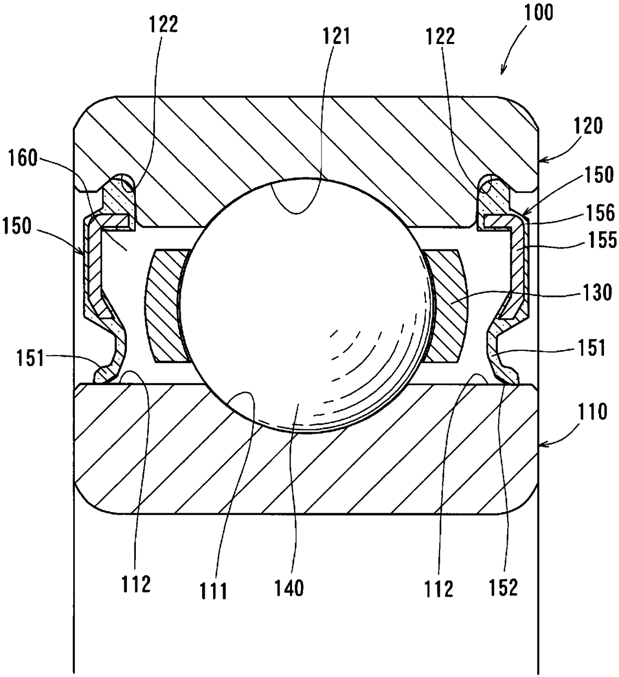
[0072] Below, based on Figure 1 to Figure 10 A first embodiment of the present invention will be described. The first embodiment corresponds to the first invention, and is an example in which the first embodiment and the second embodiment are combined.

[0073] Such as figure 1 As shown, the first embodiment becomes a sealed bearing 100, and the sealed bearing 100 includes an inner ring 110, an outer ring 120, a plurality of rolling elements 140 held by a cage 130, and the inner ring 110 and the outer ring. Two sealing members 150 between 120 seal the two ends of the inner space of the bearing. In addition, below, the direction along the bearing center axis|shaft of the sealed bearing 100 is called "axial direction." The direction perpendicular to the axial direction is called "radial direction". The circumferential direction around the central axis of the bearing is called "circumferential direction".

[0074] An annular bearing interior space 160 is formed by the inner...


PUM


Abstract

In the present invention, a plurality of protrusions (152) are formed by being arranged at intervals of 0.3-2.6 mm in the circumferential direction, on seal lips (151) of seal members (150). An oil passage (170), which interconnects a bearing inner space (160) and the outside and through which it is impossible for foreign matters of a prescribed particle size to pass, is generated between a seal sliding surface (112) sliding in the circumferential direction with respect to the protrusions (152), and the seal lips (151). Accompanying the rotation of a bearing, due to a wedge effect when the protrusions (152) draw lubricating oil into the oil passage (170) between themselves and the seal sliding surface (112), formation of an oil film is promoted between the seal lips (151) and the seal sliding surface (112), resulting in a fluid lubrication state.

Description

technical field [0001] The present invention relates to a sealed bearing including a rolling bearing and a sealing member. Background technique [0002] For example, foreign matter such as wear powder of gears is mixed in a transmission mounted in vehicles such as automobiles and various construction machines. Therefore, by using the sealing member, foreign matter is prevented from intruding into the internal space of the bearing, and premature damage of the rolling bearing is prevented. [0003] Conventionally, as rolling bearings suitable for supporting rotating parts such as transmissions and differentials mounted in vehicles such as automobiles and various construction machinery, there are ball bearings ( The following patent document 1). [0004] The ball bearing disclosed in Patent Document 1 includes an inner ring, an outer ring, and a plurality of balls interposed between track grooves of the inner ring and the outer ring, and a pair of shoulders formed on both sid...

Claims


Application Information

Patent Timeline
Patent Type & Authority Applications(China)
IPC IPC(8): F16C33/78F16C19/06F16J15/3204
CPCF16C19/163F16C33/7823F16C33/7856F16J15/3204
Inventor 稻增一刚佐佐木克明和久田贵裕水贝智洋西川健太郎宇都宫聪松本雄
Owner NTN CORP
Why Eureka
Try Eureka