
Stainless steel cutting device

A cutting device, stainless steel technology, applied in the direction of sawing machine, metal sawing equipment, metal processing, etc., can solve the problems of high labor intensity and low efficiency of workers, and achieve the effect of reducing labor intensity, streamlining operation steps and improving work efficiency

Pending Publication Date: 2018-10-30
重庆哲骁装饰工程有限公司
View PDF0 Cites 3 Cited by
  • Summary
  • Abstract
  • Description
  • Claims
  • Application Information

AI Technical Summary

Problems solved by technology

[0004] The purpose of the present invention is to provide a stainless steel cutting device to solve the problems of low efficiency and high labor intensity of existing cutting methods

Method used


Image

  • Stainless steel cutting device
  • Stainless steel cutting device
  • Stainless steel cutting device

Examples


Embodiment Construction

[0020] The following is further described in detail through specific implementation methods:

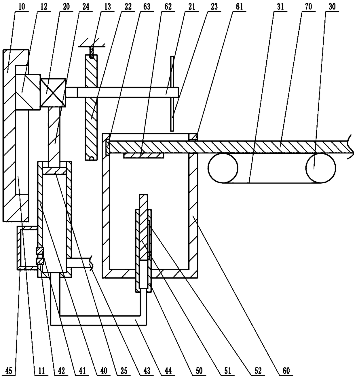
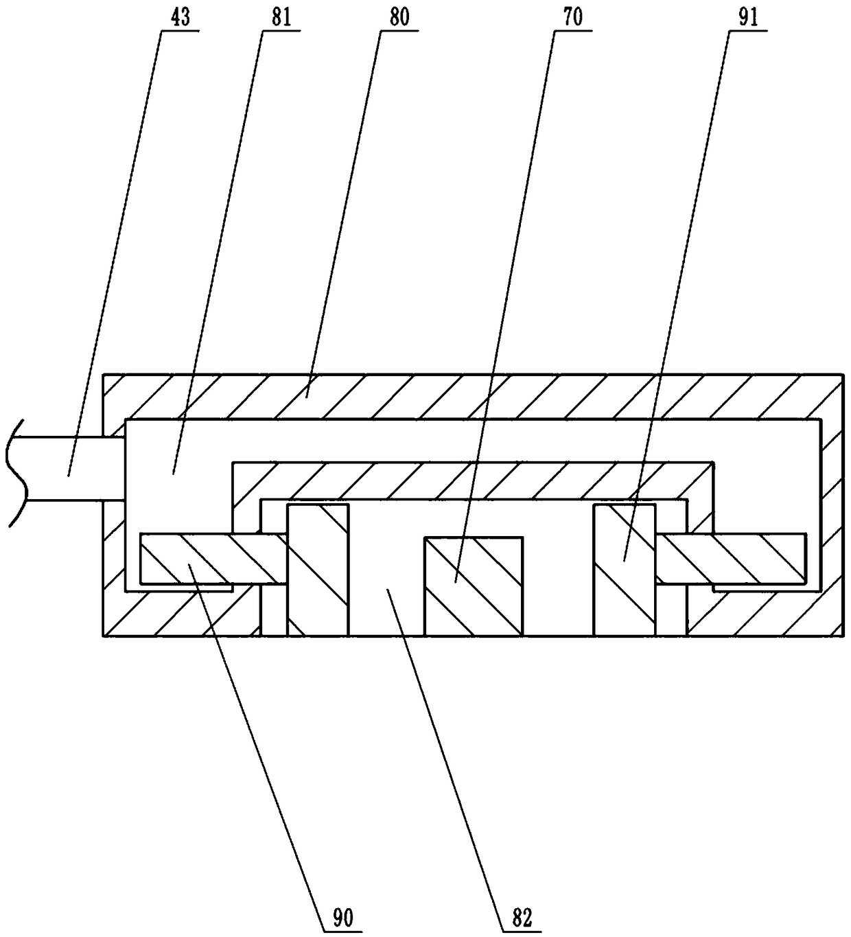
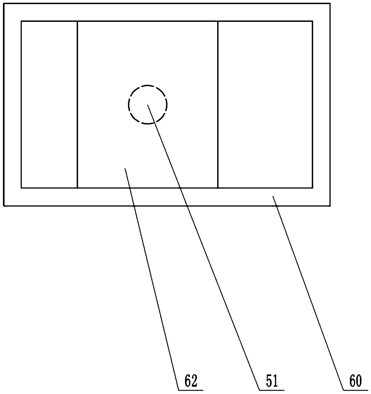
[0021] Instructions attached Figures 1 to 3 The reference signs in include: frame 10, guide groove 11, slider 12, connecting rod 13, first motor 20, rotating shaft 21, cam 22, cutting knife 23, connecting column 24, piston 25, transmission wheel 30, conveyor belt 31. Piston cylinder 40, one-way liquid inlet valve 41, one-way liquid discharge valve 42, connecting pipe 43, liquid discharge pipe 44, liquid storage tank 45, sliding cylinder 50, top column 51, limit groove 52, collection box 60, through hole 61, support plate 62, pressure sensor 63, stainless steel material 70, clamping platform 80, cavity 81, groove 82, push column 90, clamping plate 91.

[0022] Such as figure 1 As shown, the stainless steel cutting device includes a frame 10, a cutting unit, a conveying unit and a clamping unit located above the conveying unit. The cutting unit includes a first motor 20, a rotating...


PUM


Abstract

The invention belongs to the technical field of cutting machining, and particularly discloses a stainless steel cutting device. The stainless steel cutting device comprises a rack, a cutting unit, a conveying unit and a clamping unit. The cutting unit comprises a rotating shaft, a first motor, a cam and a cutting knife. The cutting knife is located above one side of the conveying unit. A guiding groove is formed in the rack. The first motor is slidably connected to the rack through the guiding groove. A sealed clamping groove is formed in the cam. A connecting rod is fixed to the rack. The clamping unit comprises a clamping table and a piston barrel. Hydraulic oil is contained inside the piston barrel. A piston is slidably connected into the piston barrel. The first motor is connected witha connecting column, wherein the lower portion of the connecting column is fixed to the piston. The piston barrel is provided with a buffer mechanism. A groove is formed in the lower surface of the clamping table. A cavity is formed in the clamping table. Two oppositely-arranged pushing columns are slidably connected into the cavity. One sides of the pushing columns are located in the groove. A connecting pipe is connected between a clamping table and the piston barrel. By using the stainless steel cutting device, the problems that an existing cutting method is low in efficiency and high in worker labor intensity can be effectively solved.

Description

technical field [0001] The invention belongs to the technical field of cutting processing, and in particular relates to a stainless steel cutting device. Background technique [0002] Stainless steel is the abbreviation of stainless steel and acid-resistant steel. It is resistant to air, steam, water and other weak corrosive media or has stainless steel. Because stainless steel is not easy to rust and has a long service life, stainless steel materials are widely used in various objects. Stainless steel is usually used in the processing and production of stainless steel, such as the production of display cabinets, doors and windows. [0003] When producing display cabinets, doors and windows, stainless steel is usually cut to make the length of stainless steel meet the requirements. However, due to the large net weight of stainless steel itself, and the original length is also long, the general method is to fix the stainless steel first, and then take a cutting The length re...

Claims


Application Information

Patent Timeline
IPC IPC(8): B23D47/06B23D47/12B23D47/08B23Q7/00
CPCB23D47/06B23D47/08B23D47/12B23Q7/00
Inventor 邓月全
Owner 重庆哲骁装饰工程有限公司
Learn More