Device for automatically separating molds

A technology of mold and rotary connection, which is applied in the field of machinery, can solve the problems of personal injury, inconvenient disassembly and assembly of the device, complex structure, etc., and achieve the effects of prolonging the service life, facilitating the placement of tools, and simple structure of the device

Inactive Publication Date: 2018-10-30
芜湖福聚模具制造有限公司
View PDF2 Cites 4 Cited by
  • Summary
  • Abstract
  • Description
  • Claims
  • Application Information

AI Technical Summary

Problems solved by technology

[0002] After the production of a variety is completed, the mold needs to be taken out from the mold sleeve. In order to save production costs in the prior art, manual knocking is often used, which is not only inefficient, but also easy to cause personal injury
[0003] The mold separation device described in the patent application number CN201720485568.6, although it saves costs, makes full use of original resources, and avoids increasing resource investment, it does not have the function of automatic mold separation, and its scope of application is relatively narrow, consuming manpower and more time cost
[0004] The patent application number is CN201720781767.1, which describes an automatic demoulding structure of a mold. Although it can realize the automatic demoulding of injection molded parts and greatly improve the demoulding efficiency of injection molded parts, its structure is very complicated and its manufacturing cost is high. Narrow application area, no labor-saving and self-locking functions, inconvenient disassembly and assembly of the device, inconvenient cleaning and transportation

Method used


Image

  • Device for automatically separating molds
  • Device for automatically separating molds

Examples


Embodiment Construction

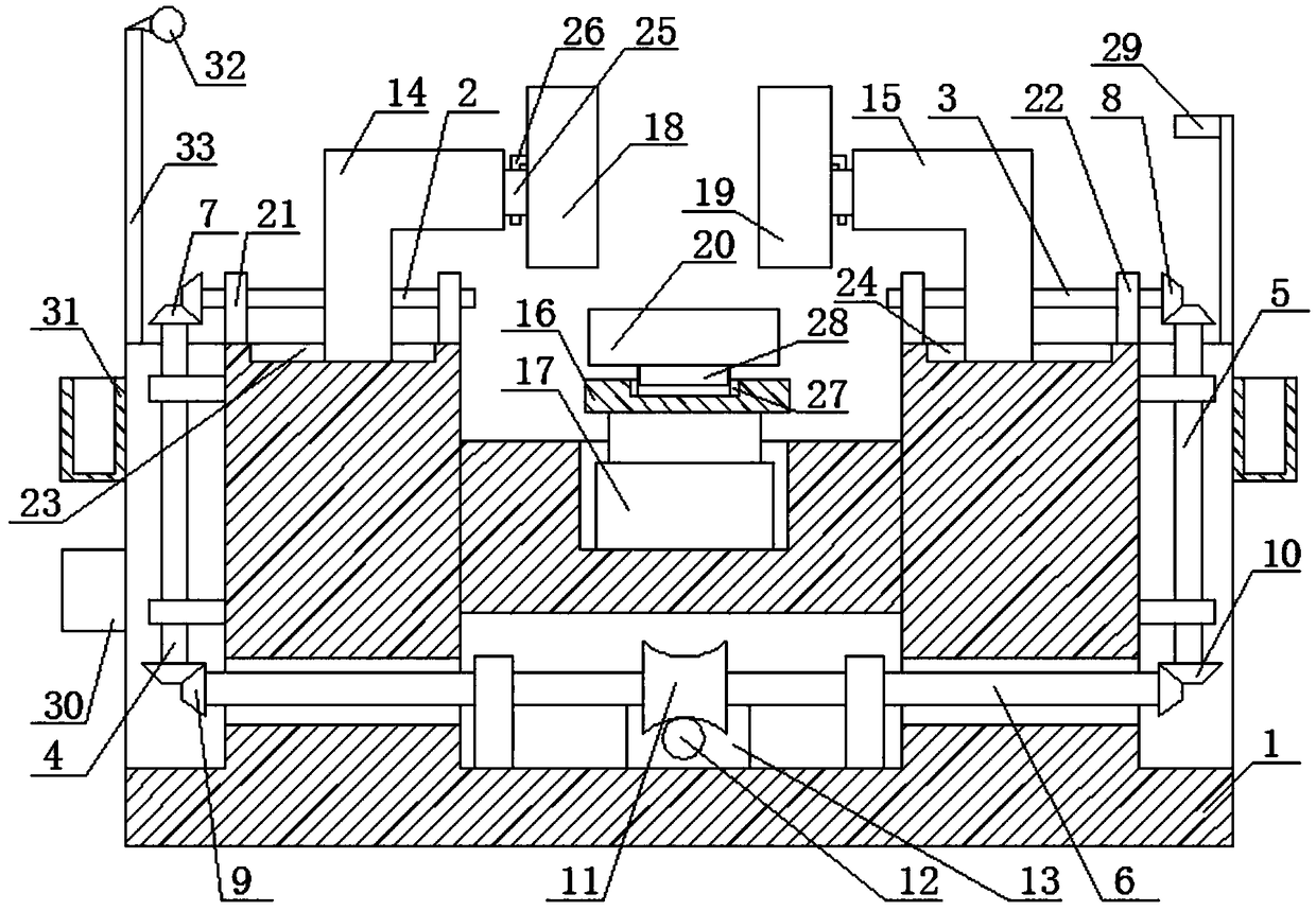
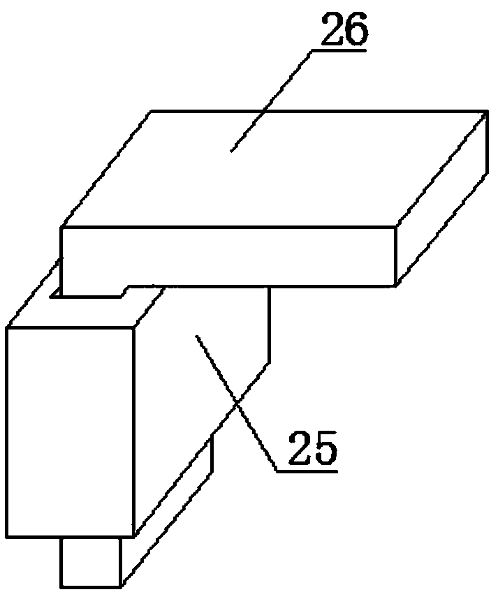
[0029] Below in conjunction with accompanying drawing, technical scheme of the present invention is described in further detail:

[0030] Such as figure 1 with figure 2 As shown, an automatic mold separation device includes support frame 1, ball screw I2, ball screw II3, shaft I4, shaft II5, shaft III6, bevel gear set I7, bevel gear set II8, bevel gear set III9, bevel Gear set IV10, turbine 11, worm 12, servo motor 13, flange I14, flange II15, fixed plate 16, hydraulic cylinder 17, left mold 18, right mold 19 and bottom mold 20; the ball screw I2 and the The ball screw II3 is rotatably connected to both sides of the top of the support frame 1 through the screw support I21 and the screw support II22 respectively, and the ball screw I2 and the ball screw II3 are collinear and arranged horizontally; the shaft I4 and the shaft II5 are respectively connected to both sides of the support frame 1 through bearing rotation, and the shaft I4 and shaft II5 are arranged parallel and ve...


PUM


Abstract

The invention discloses a device for automatically separating molds. The device comprises a supporting frame, a ball screw I, a ball screw II, a shaft I, a shaft II, a shaft III, a bevel gear set I, abevel gear set II, a bevel gear set III, a bevel gear set IV, a turbine, a worm, a servo motor, a flange I, a flange II, a fixing disc, a hydraulic cylinder, the left mold, the right mold and the bottom mold. When the device works, the servo motor is started firstly, the worm and the turbine are in engaging transmission to drive the shaft III to rotate; the shaft III drives the shaft I and the shaft II to rotate through the bevel gear set III and the bevel gear set IV; the shaft I and the shaft II drive the ball screw I and the ball screw II to rotate through the bevel gear set I and the bevel gear set II correspondingly; the ball screw I and the ball screw II drive the flange I and the flange II to relatively make linear motion correspondingly, and the left mold and the right mold are separated; and then a controller controls the servo motor to stop according to signals of a distance sensor; and finally, the hydraulic cylinder is started to drive the bottom mold to move downwards tothe set portion, and then the automatic separation process of the molds is achieved.

Description

technical field [0001] The invention relates to the mechanical field, in particular to an automatic mold separation device. Background technique [0002] After the production of a variety is finished, the mold needs to be taken out from the mold sleeve. In order to save production costs in the prior art, manual knocking is often used, which is not only inefficient, but also easily causes personal injury. [0003] The mold separation device described in the patent application number CN201720485568.6, although it saves costs, makes full use of original resources, and avoids increasing resource investment, it does not have the function of automatic mold separation, and its scope of application is relatively narrow, consuming manpower and Time cost is more. [0004] The patent application number is CN201720781767.1, which describes an automatic demoulding structure of a mold. Although it can realize the automatic demoulding of injection molded parts and greatly improve the demo...

Claims


Application Information

Patent Timeline
Patent Type & Authority Applications(China)
IPC IPC(8): B29C45/26B29C45/80B29C45/68
CPCB29C45/2673B29C45/68B29C45/80B29C2945/76568
Inventor 骆陈
Owner 芜湖福聚模具制造有限公司
Why Eureka
Try Eureka