Automatic locking and unlocking mechanism for rotating shaft system type devices

A technology of automatic locking and unlocking mechanism, applied in the direction of brake actuator, mechanical equipment, gear shifting mechanism, etc., can solve the problems of difficult to pull out the bolt, incomplete unlocking, incomplete pulling out, etc., to achieve complete unlocking, weight Light, well-structured effect

Pending Publication Date: 2018-10-30
湖南科众兄弟科技有限公司
View PDF0 Cites 1 Cited by
  • Summary
  • Abstract
  • Description
  • Claims
  • Application Information

AI Technical Summary

Problems solved by technology

The existing locking mechanism is generally a bolt-type locking mechanism. When locking, due to the existence of pin-hole fit clearance, large overload, etc., the shafting will still rotate slightly, so it is impossible to maintain the extremely high circumferential positi

Method used


Image

  • Automatic locking and unlocking mechanism for rotating shaft system type devices
  • Automatic locking and unlocking mechanism for rotating shaft system type devices
  • Automatic locking and unlocking mechanism for rotating shaft system type devices

Examples


Embodiment Construction

[0022] The following examples are further explanations and illustrations of the present invention, and do not constitute any limitation to the present invention.

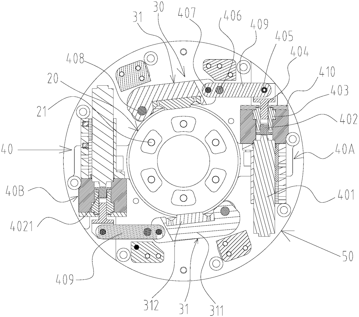
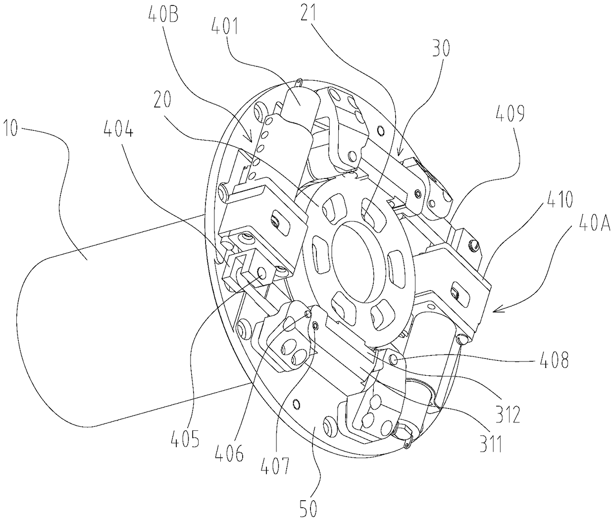
[0023] refer to figure 1 , figure 2 , The automatic locking and unlocking mechanism of the rotating shaft equipment of the present invention includes a rotating shaft 10 , a friction disc 20 , a friction plate assembly 30 , a driving mechanism 40 and a base 50 .

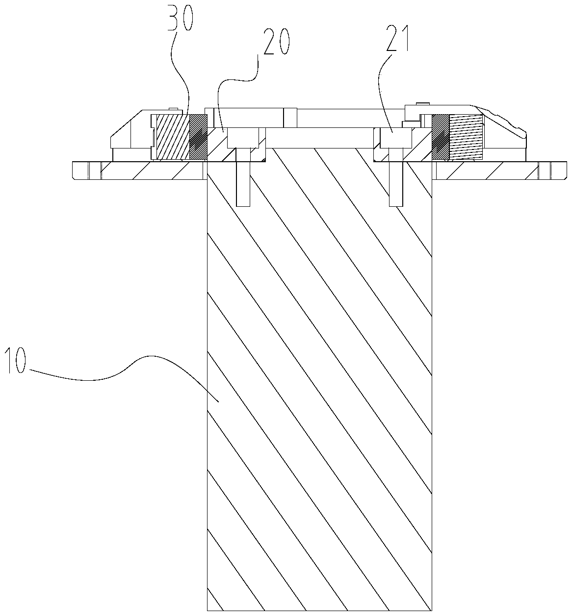
[0024] In the present invention, the rotating shaft 10 is the rotating shaft of some kind of rotating equipment, such as the rotating shaft of the known precision turntable and the rotating strapdown inertial group rotating shaft. In this example, if image 3 One end of the illustrated rotating shaft is connected to the rotating device and the other end is connected to the friction disc 20 . In the present invention, the rotating shaft 10, the friction disc 20, the friction plate assembly 30, and the driving mechanism 40 are all arranged on the base 50...


PUM


Abstract

The invention discloses an automatic locking and unlocking mechanism for rotating shaft system type devices. The mechanism comprises a rotating shaft, a friction disc, friction plate assemblies and driving mechanisms; the rotating shaft is arranged on a rotating device; the friction disc is fixed to the end of the rotating shaft and synchronously rotates with the rotating shaft; the friction plateassemblies are symmetrically arranged on the outer surface of the friction disc and can move in the radial direction to be attached to or leave from the friction disc; and the driving mechanism is connected with the friction disc to push the friction plate assemblies to move in the radial direction, when the rotating shaft in operation needs to be braked, the driving mechanism pushes the frictionplate assemblies to move towards the axis of the rotating shaft and brakes the friction disc to lock the rotating shaft, and when the driving mechanism pushes the friction plate assemblies to move inthe direction of being far away from the axis of the rotating shaft to enable the friction plate assemblies and the friction disc to be separated, the rotating shaft is unlocked. The automatic locking and unlocking mechanism for the rotating shaft system type devices has the characteristics that the structure is reasonable, locking is reliable, unlocking is thorough, the responding speed is high,the size is small, and the weight is low.

Description

【Technical field】 [0001] The invention relates to the technical field of braking, in particular to an automatic locking and unlocking mechanism for rotating shaft equipment. 【Background technique】 [0002] At present, various types of rotating equipment are widely used in the industrial and technological fields. The rotating equipment is provided with a rotating shaft, and the equipment rotates around the axis. In use, this type of equipment needs to brake and control the rotating shaft system according to the design and use requirements, so as to lock or unlock the rotating shaft, so that it can stop or start operation precisely according to the design or control requirements, especially aerospace equipment The small and medium-sized rotating shafting systems in China all involve the braking control of the rotating shaft, which automatically locks or unlocks the rotating shafting system through a locking mechanism. The existing locking mechanism is generally a bolt-type lo...

Claims


Application Information

Patent Timeline
IPC IPC(8): F16D49/18F16D65/14F16D121/14F16D121/24
CPCF16D49/18F16D65/14F16D2121/14F16D2121/24
Inventor 肖剑峰敖勤
Owner 湖南科众兄弟科技有限公司
Why Eureka
Try Eureka