
Thin-walled rotating member flange face drilling and milling fixture

A technology of thin-wall rotation and flange surface, which is applied in the direction of clamping, manufacturing tools, metal processing machinery parts, etc., can solve the problems of affecting the processing quality of workpieces, large clamping deformation, complicated operation, etc., and achieves simple structure and reduced The effect of high deformation and high precision

Active Publication Date: 2018-11-02
HUNAN UNIV
View PDF14 Cites 8 Cited by
  • Summary
  • Abstract
  • Description
  • Claims
  • Application Information

AI Technical Summary

Problems solved by technology

[0004] The above-mentioned fixture is mainly used for the outer circle processing of thin-walled rotary parts, and the operation is relatively complicated
Existing fixtures for thin-walled rotary parts are less suitable for end face processing, and most of the auxiliary supports are rigid rods, resulting in large clamping deformation and affecting the processing quality of the workpiece

Method used


Image

  • Thin-walled rotating member flange face drilling and milling fixture
  • Thin-walled rotating member flange face drilling and milling fixture
  • Thin-walled rotating member flange face drilling and milling fixture

Examples


Embodiment Construction

[0032] The present invention will be described in detail below with reference to the accompanying drawings and examples. It should be noted that, in the case of no conflict, the embodiments of the present invention and the features in the embodiments can be combined with each other. For the convenience of description, if the words "up", "down", "left" and "right" appear in the following, it only means that the directions of up, down, left and right are consistent with the drawings themselves, and do not limit the structure.

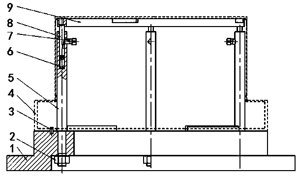
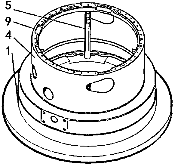
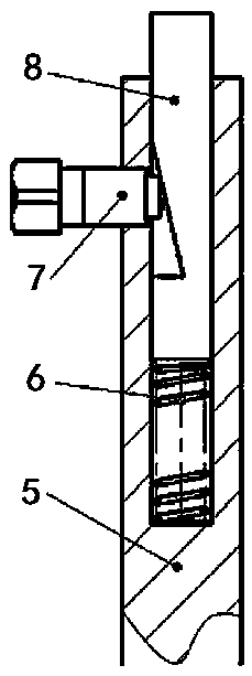
[0033] A drilling and milling fixture for the flange surface of a thin-walled rotary part, such as figure 1 As shown, it includes a support ring 9, a base 1, a positioning pin 3 and an adaptive height adjustment structure; wherein, the limit platform on the base and the positioning pin 3 limit the position of the thin-walled rotary member, so that the The hole system corresponds to the die hole on the support ring one by one. In order to avoid the drill...


PUM


Abstract

The invention discloses a thin-walled rotating member flange face drilling and milling fixture. The thin-walled rotating member flange face drilling and milling fixture comprises a base, a plurality of support rods mounted on the base and a support ring mounted on the top ends of the multiple support rods. A self-adaptive height-adjusting structure for adjusting the supporting height and maintaining the height is arranged between the support ring and the support rods, so that the top surface of the support ring is tightly attached to the lower bottom surface of a ring flange of a thin-walled rotating member. The base is provided with a limiting structure for limiting the lower end position of the thin-walled rotating member, and the support ring is provided with an avoiding groove corresponding to a flange face notch to be processed of the thin-walled rotating member and die holes corresponding to hole series to be processed of the flange surface. The thin-walled rotating member flangeface drilling and milling fixture can design a reasonable fixture structure according to the processing characteristics of the flange face, and the operation of processing personnel is facilitated.

Description

technical field [0001] The invention relates to a fixture for drilling and milling (drilling and milling) the flange surface of a thin-walled rotary part, in particular to a special fixture for processing the notch and hole system of the flange surface of a thin-walled rotary part, and belongs to the technical field of mechanical special fixture manufacturing. Background technique [0002] Thin-walled rotary parts have been widely used in industrial engineering, especially in the field of aerospace, because of their compact structure, light weight, and material saving. Some thin-walled rotary parts in the aerospace field have poor rigidity; the materials used are difficult-to-machine materials with high strength, high wear resistance and high heat resistance. Therefore, these parts are prone to elastic or plastic deformation due to the action of cutting force, cutting heat and clamping force during processing, which affects the processing quality. [0003] For the fixture d...

Claims


Application Information

Patent Timeline
Patent Type & Authority Applications(China)
IPC IPC(8): B23Q3/06
CPCB23Q3/065
Inventor 王伏林谢晖龚志辉徐磊磊胡嘉豪吕榛刘爱阳嵇佳佳陈张宁顺提
Owner HUNAN UNIV
Learn More