
Performance detection device for ejection control mechanism and application method thereof

A control mechanism and detection device technology, which is applied in the direction of ejection/departure device, aircraft component testing, etc., can solve the problems affecting the repair quality of the ejection control mechanism, the difficulty of accurate measurement, and the low test accuracy, so as to overcome the single performance detection and repair. Reliable quality, the effect of solving large errors

Inactive Publication Date: 2018-11-02
芜湖天航装备技术有限公司
View PDF0 Cites 0 Cited by
  • Summary
  • Abstract
  • Description
  • Claims
  • Application Information

AI Technical Summary

Problems solved by technology

Most of the existing testing equipment for ejection control mechanisms are discrete and simple equipment. Each testing equipment can only complete a single function testing work. To conduct a comprehensive testing of it, two to three sets of different testing equipment need to work together to complete. , the test efficiency is low, and the test accuracy is not high
In addition, when measuring the working stroke of the ejection control system wire rope in the ejection control mechanism, since the ejection control system wire rope automatically and quickly returns to the initial position after being retracted in place, the maintenance personnel cannot use visual and traditional detection methods in extreme Accurately measuring the actual working stroke in a short period of time can only be estimated, and there are certain difficulties in accurate measurement, which greatly affects the repair quality of the ejection control mechanism and seriously inhibits the improvement of the ejection control mechanism's repair capability and production capacity

Method used


Image

  • Performance detection device for ejection control mechanism and application method thereof
  • Performance detection device for ejection control mechanism and application method thereof

Examples


Embodiment Construction

[0027] In order to make the technical means, creative features, goals and effects achieved by the present invention easy to understand, the present invention will be further elaborated below.

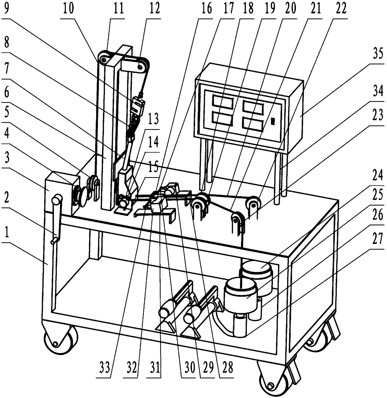
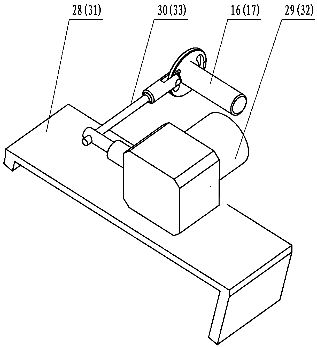
[0028] Such as figure 1 and figure 2 As shown, a performance detection device for an ejection control mechanism includes a work cabinet 1 and an electrical control box assembly arranged on the work cabinet 1. The work cabinet 1 is provided with a reducer assembly for providing power and controlling speed. The work cabinet 1 is also provided with a fixed bracket assembly, the fixed bracket assembly is provided with a cable assembly for power transmission that cooperates with the reducer assembly, and the cable assembly is provided with a handle tooling 8, An angular displacement sensor assembly is arranged on the fixed bracket assembly, a first displacement sensor assembly and a second displacement sensor assembly cooperating with the angular displacement sensor assembly are arranged o...


PUM


Abstract

The invention relates to a performance detection device for ejection control mechanisms and application method thereof, the performance detection device comprises a working cabinet and an electric control box component, a fixing bracket component is also arranged on the working cabinet, and a steel cable component is arranged on the fixed support component; a handle tooling is arranged on the steel cable component, and an angular displacement sensor is arranged on the fixing bracket component; a first displacement sensor component and a second displacement sensor component matched with the angular displacement sensor component are arranged on the working cabinet, and a first counterweight component and a second counterweight component matched with the first displacement sensor component and the second displacement sensor component are arranged inside the working cabinet, the method comprises the following steps: (1) mounting the ejection control mechanism; (2) connecting the handle; (3) connecting counterweight and sensing; (4) electrifying; (5) shaking the handle; (6) measuring values; and (7) recording working stroke, according to the performance detection device, the detection of the handle of the ejection control mechanism is realized on the same device.

Description

technical field [0001] The invention relates to the field of aviation equipment detection, in particular to a device for detecting the performance of an ejection control mechanism and a method for using the same. Background technique [0002] At present, the ejection seat used for pilot's life-saving is generally used on modern domestic and foreign fighter planes, fighter jets and some small civil aircraft. The aircraft ejection seat is one of the important components of the ejection life-saving device. It is a special aviation life-saving equipment to ensure that the pilot successfully completes the task and ejects the pilot from the aircraft and makes it land safely in an emergency. It is the "life chair" for the pilot at critical moments. It is also the final guarantee of the pilot, and its integrity rate and function will directly affect the survivability of the pilot. [0003] The ejection control mechanism is a key and important part of the aircraft ejection seat. The...

Claims


Application Information

Patent Timeline
Patent Type & Authority Applications(China)
IPC IPC(8): B64F5/60B64D25/08
CPCB64D25/08B64F5/60
Inventor 章艳肖海波汤忠苗王建民郝明
Owner 芜湖天航装备技术有限公司
Learn More