Trigger device of over-speed governor

A technology of triggering device and speed limiter, which is applied in the direction of transportation, packaging, elevators, etc., can solve the problems of inconvenient detection, hidden dangers of elevator safe operation, and failure to guarantee the reliability of braking devices, etc., so as to improve safety and reliability. Design features, convenience-enhancing effects

Pending Publication Date: 2018-11-02
HANGZHOU HUNING ELEVATOR PARTS CO LTD
View PDF5 Cites 0 Cited by
  • Summary
  • Abstract
  • Description
  • Claims
  • Application Information

AI Technical Summary

Problems solved by technology

At this time, since the centrifugal speed limiter will only trigger the throwing block to perform centrifugal movement when the speed of the car exceeds the limited speed, in the elevator without machine room, the maintenance personnel cannot artificially trigger the throwing block, which is inconvenient for those who do not reach the rated speed. The sensitivity of the speed limit of the elevator speed limiter is detected, and the reliability of the braking device cannot be guaranteed.
At the same time, during the actual operation of the machine room-less elevator, if the car exceeds the set detection speed and the throwing block is still not triggered to produce centrifugal motion, the verification of the speed limiter, safety gear and linkage mechanism will not be completed. The subsequent safe operation of the elevator caused serious safety hazards

Method used


Image

  • Trigger device of over-speed governor
  • Trigger device of over-speed governor
  • Trigger device of over-speed governor

Examples


Embodiment 1

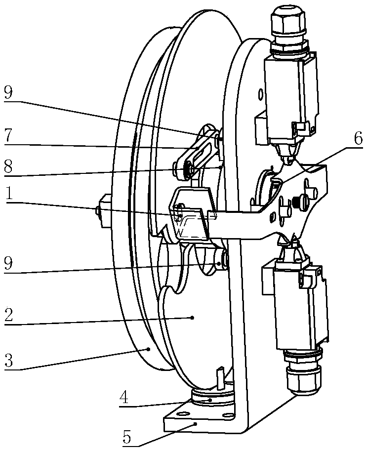
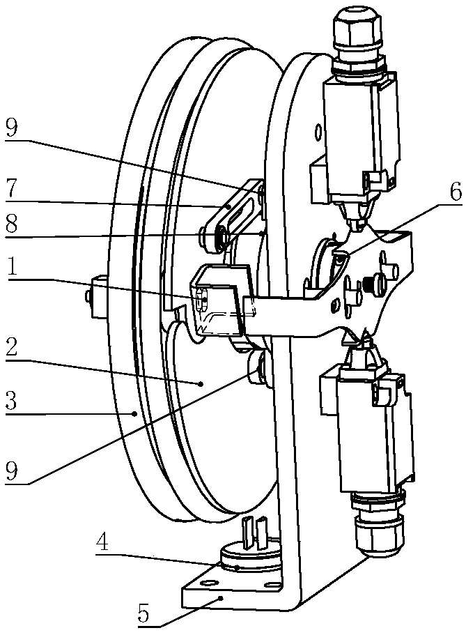
[0040] Such as Picture 1-1 As shown, the speed governor trigger device includes a rope wheel 3, a main shaft 6, and a main shaft 6 is installed in the middle of the rope wheel 3, and two centrifugal weights 2 are arranged symmetrically on the rope wheel 3, and the two centrifugal weights can perform synchronous centrifugal movement; it also includes an electromagnetic trigger The mechanism 4 and the electromagnetic trigger mechanism 4 are installed in the position corresponding to the centrifugal weight 2 . When the electromagnetic trigger mechanism 4 is energized, a closed magnetic circuit is formed between the electromagnetic trigger mechanism 4 and the centrifugal weight 2, and the centrifugal weight 2 generates centrifugal motion under the action of electromagnetic force.

[0041]Specifically, in this embodiment, the overspeed governor trigger device also includes a vertical plate 5, the main shaft 6 is installed on the vertical plate 5, and the electromagnetic trigger mec...

Embodiment 2

[0059] Such as Figure 5-1 As shown, compared with Embodiment 1, the speed governor trigger device shown in this embodiment is mainly different in the shape of the centrifugal weight and the linkage mechanism. The speed governor shown in this embodiment is the most advanced in the prior art. The common speed limiter structure will not elaborate on its specific composition here.

[0060] Specifically, in this embodiment, the electromagnetic trigger mechanism 4 adopts Figure 7 According to the structure shown in g, according to the requirements of different working conditions, the electromagnetic trigger mechanism 4 described in this embodiment can also adopt such as Figure 7 Any structure shown in a-7k.

[0061] The triggering principle of the overspeed governor shown in this embodiment is exactly the same as that in Embodiment 1, that is, when the electromagnetic trigger mechanism 4 is energized, a closed magnetic circuit is formed between the electromagnetic trigger mecha...

Embodiment 3

[0063] Such as Figure 6-1 As shown, the speed governor trigger device includes a rope wheel 3, a main shaft 6, and a main shaft 6 is installed in the middle of the rope wheel 3, and two centrifugal weights 2 are arranged symmetrically on the rope wheel 3, and the two centrifugal weights can perform synchronous centrifugal movement; it also includes an electromagnetic trigger The mechanism 4 and the electromagnetic trigger mechanism 4 are installed in the position corresponding to the centrifugal weight 2 . When the electromagnetic trigger mechanism 4 is energized, a closed magnetic circuit is formed between the electromagnetic trigger mechanism 4 and the centrifugal weight 2, and the centrifugal weight 2 generates centrifugal motion under the action of electromagnetic force.

[0064] Specifically, in this embodiment, the overspeed governor trigger device also includes a vertical plate 5, the main shaft 6 is installed on the vertical plate 5, and the electromagnetic trigger me...


PUM


Abstract

The invention provides a trigger device of an over-speed governor, and belongs to the field of elevators. The trigger device of the over-speed governor comprises a rope wheel and a main shaft, whereinthe main shaft is arranged in the middle of the rope wheel; two centrifugal weights are symmetrically arranged on the rope wheel, and can perform synchronous centrifugal motion; and the trigger device of the over-speed governor further comprises an electromagnetic trigger mechanism, the electromagnetic trigger mechanism is arranged at the position corresponding to the centrifugal weights. When the electromagnetic trigger mechanism is electrified, the electromagnetic trigger mechanism forms a closed magnetic circuit with one of the two centrifugal weights, and the centrifugal weights generatecentrifugal motion under the action of electromagnetic force. According to the trigger device of the over-speed governor, the electromagnetic trigger mechanism is arranged to facilitate operators to remotely trigger the over-speed governor, so that the annual inspection and testing requirements are met; when the sensitivity of the over-speed governor needs to be detected below the rated speed, only the electromagnetic trigger mechanism needs to be switched on, so that the centrifugal weights generate centrifugal motion, the action of the over-speed governor is triggered, the convenience of detecting the of over-speed governor a machine-room-free elevator is greatly improved, and the remote operation is simple and convenient.

Description

technical field [0001] The invention relates to a speed governor trigger device, which is suitable for the field of elevators. Background technique [0002] The speed limiter is used to detect the running speed of the elevator car. When the elevator descends overspeed or falls, the movement of the elevator is controlled by an electrical safety switch. When the speed exceeds 115% of the rated speed of the elevator, the wire rope on the speed limiter passes through The pull mechanism triggers the linkage safety gear, and the safety gear acts as an emergency braking protection device to brake the overspeeding and falling car in the downward direction, thereby protecting the safety of the elevator. [0003] The national standard GB / T7588-2003, 9.9.8.3 stipulates that "when the following conditions are met, it is not necessary to meet the requirements of 9.9.8.2: a) the method of remote control (except wireless) can be used from outside the hoistway to realize the requirements of...

Claims


Application Information

Patent Timeline
Patent Type & Authority Applications(China)
IPC IPC(8): B66B5/06
CPCB66B5/044B66B5/06
Inventor 邹家春孟红星李密何新何文晖
Owner HANGZHOU HUNING ELEVATOR PARTS CO LTD
Why Eureka
Try Eureka