Gravity tensioning device

A tensioning device and gravity technology, applied in hoisting devices, clockwork mechanisms, etc., can solve the problems of increasing the complexity of the ground power generation system, increasing the area occupied by the ground power generation system, and the structure of the ground power generation system. The effect of small footprint, simple structure, and reduced layout difficulty

Active Publication Date: 2018-11-02
芜湖天风新能源科技有限公司
View PDF16 Cites 2 Cited by
  • Summary
  • Abstract
  • Description
  • Claims
  • Application Information

AI Technical Summary

Problems solved by technology

However, this solution increases the complexity of the ground power generation system by adding a cable buffer device, which makes the structure of the whole ground power generation system cumbersome and increases the floor area of ​​the ground power generation system. Each section adds a lot of difficulty
At the same time, the pulley blocks of the cable buffering device are arranged side by side, and the buffering capacity is relatively small.

Method used


Image

  • Gravity tensioning device
  • Gravity tensioning device
  • Gravity tensioning device

Examples


Embodiment 1

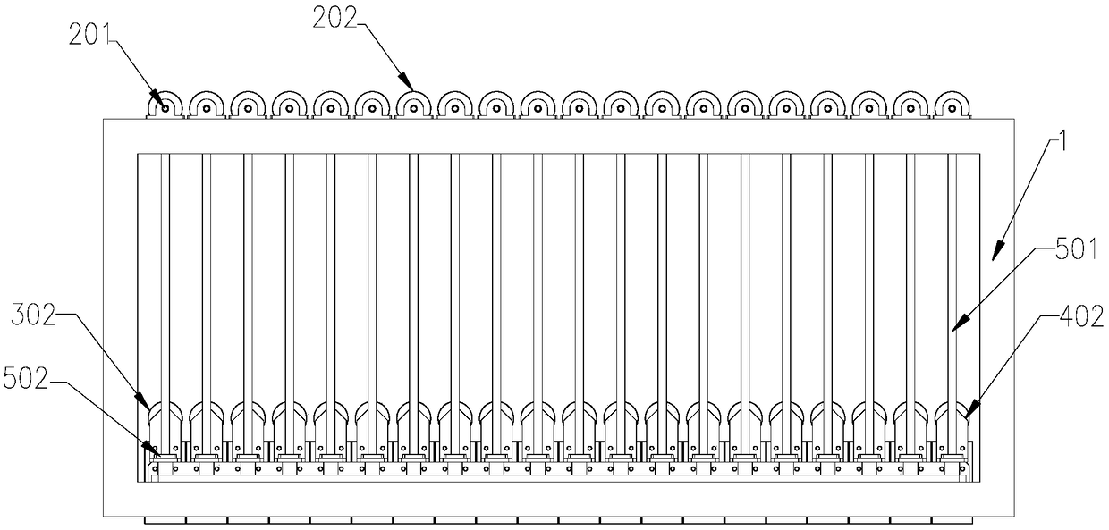
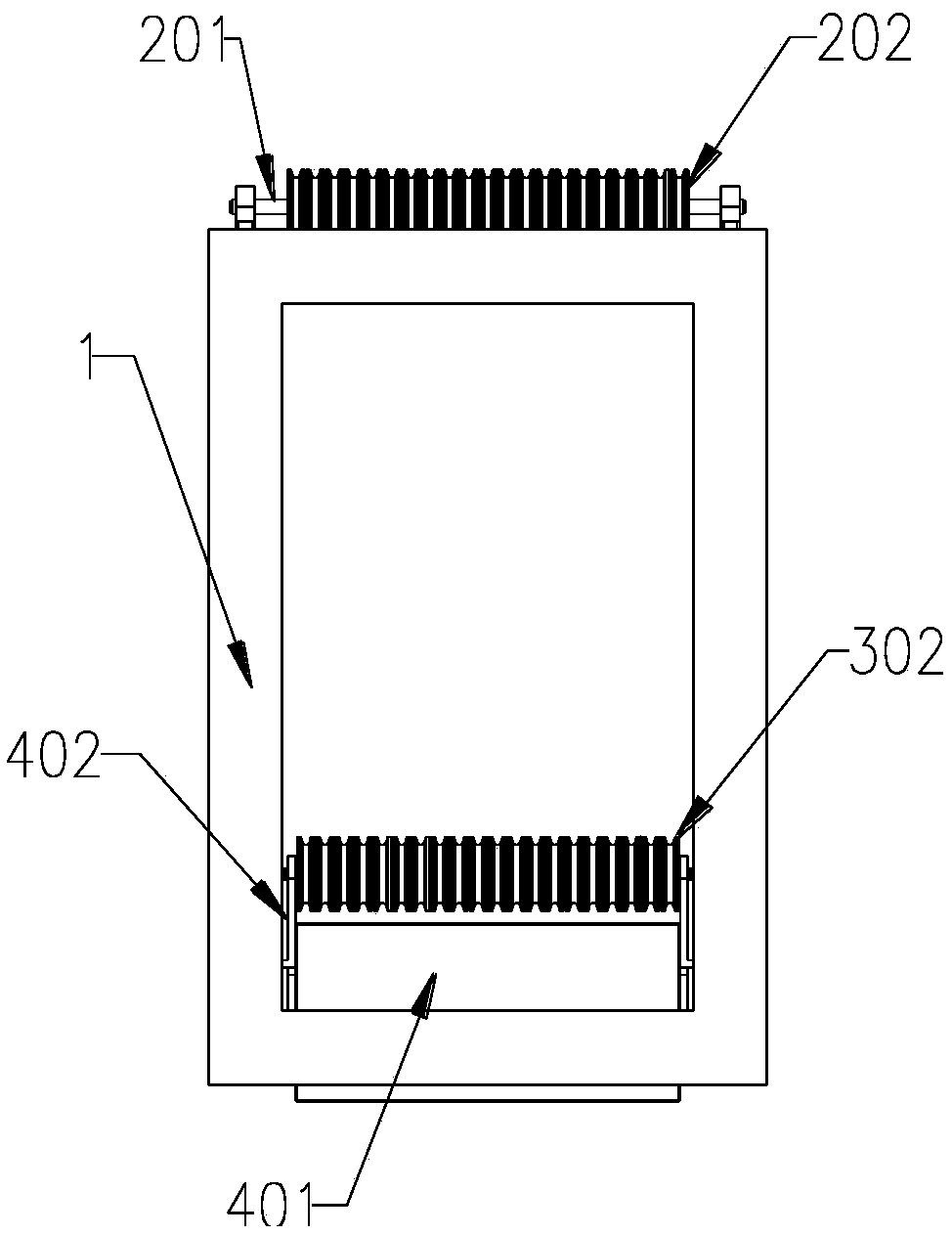
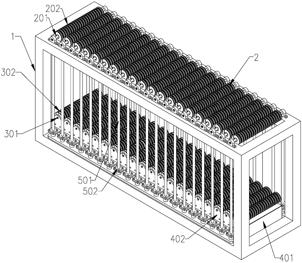
[0028] Such as Figure 1~3 As shown, this embodiment provides a gravity tensioning device, which is mainly used in the field of high-altitude wind power generation. Frame 1 bottom, movable pulley block 3 that is arranged in parallel; Described fixed pulley block 2 comprises the first fixed shaft 201 that is installed on the described frame, and some fixed pulleys 202 are installed on the described first fixed shaft 201; Described movable pulley block It includes a second fixed shaft 301 on which a number of movable pulleys 302 are installed; a row of the fixed pulleys 202 corresponds to a row of the movable pulleys 302 .

[0029] Specifically, each fixed pulley and each movable pulley in the corresponding fixed pulley block and movable pulley block also correspond to each other respectively. As a preferred situation, the corresponding fixed pulleys and movable pulleys are on the same vertical plane. Assuming that the corresponding fixed pulley and movable pulley are a pulley ...

Embodiment 2

[0039] This embodiment provides a gravity tensioning device, which is mainly used in the field of high-altitude wind power generation. On the first fixed shaft, a number of fixed pulleys are installed on the first fixed shaft; it also includes a number of movable pulleys arranged at the lower part of the frame, and the movable pulleys correspond to the fixed pulleys; each movable pulley is also connected with a counterweight, counterweight The overall trend is light at the front and heavy at the end.

[0040] Among them, for the gravity tensioning device, the cable is wound one by one from the entrance of the rope, one fixed pulley and one movable pulley, and finally fixed on the last movable pulley / fixed pulley. Therefore, the fixed pulley / moving pulley wound first is the front, The final fixed pulley / moving pulley is the rear.

[0041] The weight of the counterweight of the movable pulley increases evenly from front to back. Specifically, the counterweight of the movable p...


PUM


Abstract

The invention relates to the field of high-altitude wind power generation, and particularly discloses a gravity tensioning device. The device further comprises several fixed pulley sets arranged parallelly and fixed to the upper portion of a rack and several movable pulleys arranged at the lower portion of the rack, wherein the fixed pulley sets comprise first fixed shafts installed on the rack, and several fixed pulleys are installed on the first fixed shafts; the movable pulleys are in one-to-one correspondence with the fixed pulleys and are further connected with balance weights, and the whole balance weights are in a tendency that the front portions are light, and the back portions are heavy. Compared with the prior art, the provided gravity tensioning device is a cable storage devicewith a cable buffering function, the buffering capacity is large, frictional loss of cables is less, and the device is beneficial for prolonging the service life of the cables.

Description

technical field [0001] The invention relates to the field of high-altitude wind power generation, in particular to a gravity tensioning device. Background technique [0002] Wind energy is a clean and renewable energy source, and the wind energy stored in the sky is more than 100 times the total energy demand of human society. High-altitude wind energy has the characteristics of high wind speed, high average energy density, wide geographical distribution, high stability, and continuous operation all year round. How to make full use of high-altitude wind energy for human use is a hot topic that scientific researchers have been paying attention to. The many advantages of high-altitude wind energy have also attracted more and more attention from all over the world. [0003] The utilization of high-altitude wind energy is to collect wind energy at high altitude, convert the wind energy into mechanical energy, and finally convert the mechanical energy into electrical energy or o...

Claims


Application Information

Patent Timeline
IPC IPC(8): B66D1/50B66D1/36
CPCB66D1/36B66D1/50
Inventor 张建军
Owner 芜湖天风新能源科技有限公司
Why Eureka
Try Eureka