
Apparatus to filter and purify water

A technology for filtering, purifying and purifying water, applied in the fields of filtration treatment, multi-stage water treatment, chemical instruments and methods, etc., can solve the problems of high power consumption, inability to obtain effects, limited purification effect, etc., to save power and facilitate use , the effect of maximizing the filtering effect

Pending Publication Date: 2018-11-02
CITIC DICASTAL
View PDF1 Cites 2 Cited by
  • Summary
  • Abstract
  • Description
  • Claims
  • Application Information

AI Technical Summary

Problems solved by technology

However, existing water filtration and purification devices often have the characteristics of high power consumption, limited purification effect, and the need for additional pressurization, etc.
The above characteristics may make it difficult to use conventional purifiers to purify water in some areas with low water pressure, or the desired effect cannot be achieved after using conventional purifiers to purify water

Method used


Image

  • Apparatus to filter and purify water
  • Apparatus to filter and purify water
  • Apparatus to filter and purify water

Examples


Embodiment 1

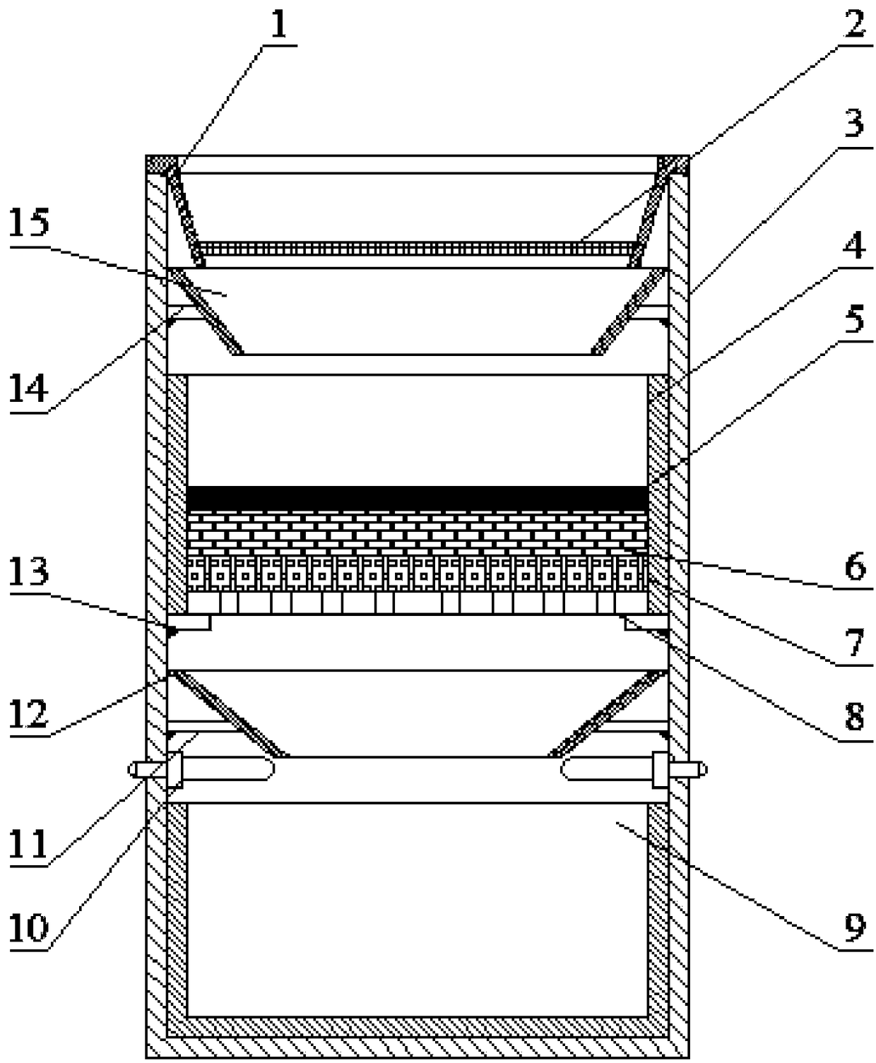
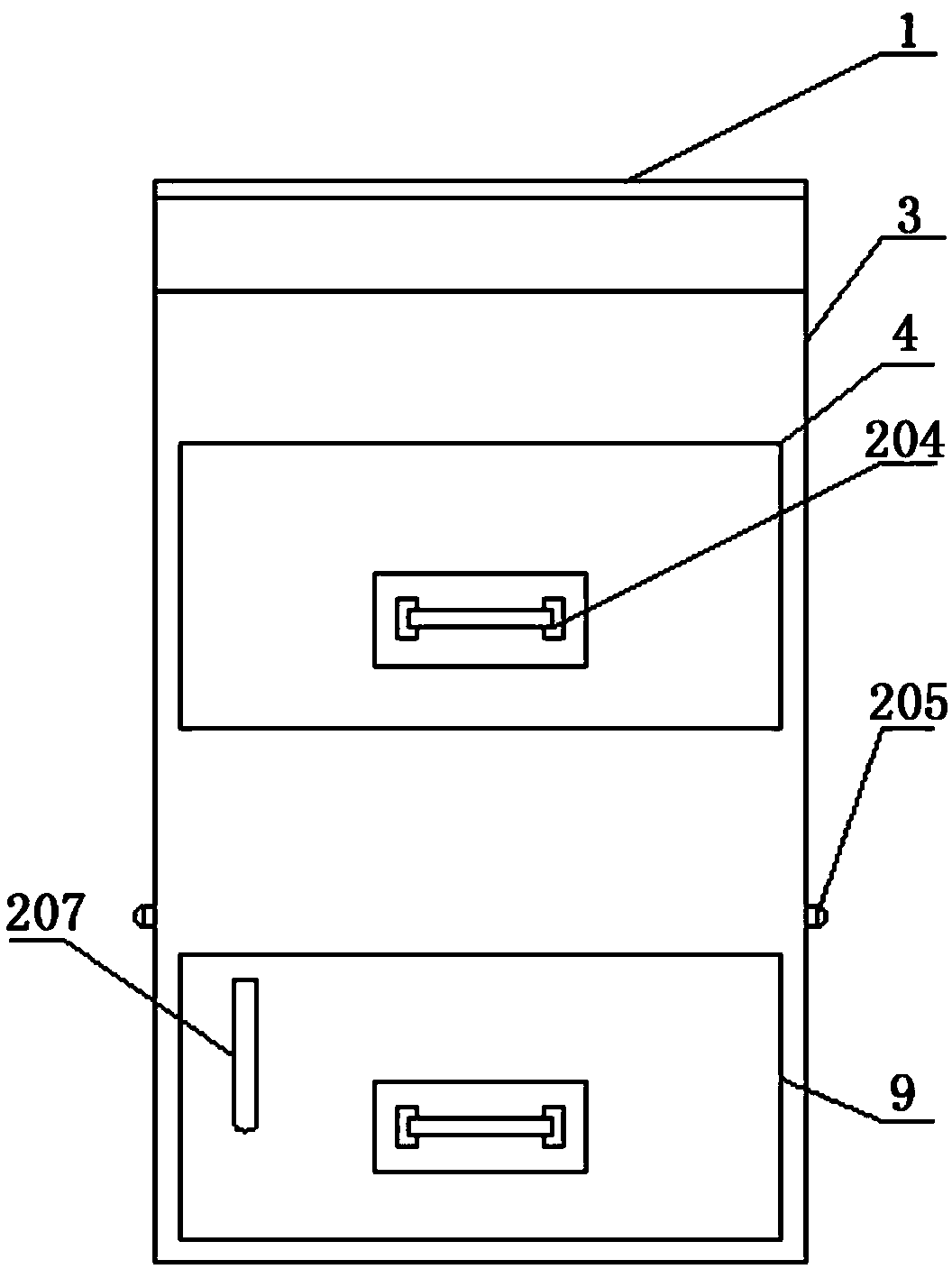
[0023] The device includes a coarse filter box (1), a filter screen (2), a main box body (3), a filter material box body (4), an anthracite filter material layer (5), a quartz sand filter material layer (6), an activated carbon layer (7), filter material bottom plate (8), purified water collection box (9), ultraviolet light for killing viruses (10), 2# liquid collector support beam (11), 2# liquid collector (12), filter material box support Beam (13), 1# liquid collector support beam (14) and 1# liquid collector (15), and the coarse filter box (1) that comprises filter screen (2) is arranged successively from top to bottom in the main casing, The 1# liquid collector (15) supported by the support beam (14) of the 1# liquid collector includes an anthracite filter material layer (5), a quartz sand filter material layer (6), an activated carbon layer (7), and a filter material bottom plate (8) and the filter box casing (4) of the filter box support beam (13), the 2# liquid collect...

Embodiment 2

[0027] In this embodiment, various settings are basically the same as those in Embodiment 1, the difference being that the anthracite filter material layer (5) is composed of anthracite filter material with an average diameter of 1.2mm and a thickness of 4mm. The quartz sand filter material layer (6) is composed of quartz sand filter material with an average diameter of 1 mm and a thickness of 4 mm. The activated carbon filter material layer (7) is composed of activated carbon filter material with an average diameter of 2 mm and a thickness of 4 mm.

Embodiment 3

[0029] In this embodiment, various settings are basically the same as in Embodiment 1, the difference is that the anthracite filter material layer (5) is composed of anthracite filter material with an average diameter of 2 mm and a thickness of 6 mm. The quartz sand filter material layer (6) is composed of quartz sand filter material with an average diameter of 2mm and a thickness of 6mm. The activated carbon filter material layer (7) is composed of activated carbon filter material with an average diameter of 4mm and a thickness of 6mm.


PUM

PropertyMeasurementUnit
The average diameteraaaaaaaaaa
Thicknessaaaaaaaaaa
The average diameteraaaaaaaaaa

Abstract

The invention provides an apparatus to filter and purify water, comprising tank body (1), as well as a coarse filtering device, a fine filtering device, an ultraviolet sterilizing device and a purified water collection device which are mounted vertically in the tank body (1) in sequentially arranged manner. The apparatus is characterized in that the coarse filtering device includes filter mesh (2); the fine filtering device includes anthracite filter layer (5), quartz sand filter material layer (6) and activated carbon filter material layer (7) which are arranged in sequence. The apparatus hasthe advantages that the multiple filter layers are reasonably allocated to maximize the filtering effect, the filter layers are arranged in vertical direction such that water can flow down under thegravity effect, and electricity is saved.

Description

technical field [0001] The invention relates to the field of water purification, in particular to a device for filtering and purifying water. Background technique [0002] In industry and life, it is necessary to treat naturally obtained water or domestic sewage to obtain high-quality purified water. In practice, water treatment devices such as filtration and reverse osmosis are often used to treat water. However, existing water filtration and purification devices often have the characteristics of high power consumption, limited purification effect, and the need for additional pressurization. The above characteristics may make it difficult to use conventional purifiers to purify water in some areas with low water pressure, or the desired effect cannot be achieved after using conventional purifiers to purify water. Contents of the invention [0003] Therefore, the object of the present invention is to provide a device for filtering and purifying water with low power consu...

Claims


Application Information

Patent Timeline
IPC IPC(8): C02F9/08
CPCC02F1/001C02F1/32C02F2303/04C02F2301/08
Inventor 黄亮张福旺刘宏磊张宝许斌杨倩
Owner CITIC DICASTAL
Features
  • Generate Ideas
  • Intellectual Property
  • Life Sciences
  • Materials
  • Tech Scout
  • Unparalleled Data Quality
  • Higher Quality Content
  • 60% Fewer Hallucinations
Learn More