Special drafting spinning mechanism for spinning frame

A spinning frame and drafting technology, which is applied in the field of special drafting and spinning mechanisms for spinning frames, can solve problems such as low spinning efficiency, apron drop, tailing, etc., and achieve the effect of improving yarn quality and spinning efficiency

Pending Publication Date: 2018-11-02
WUXI HENGJIU ELECTRICAL TECH
View PDF6 Cites 4 Cited by
  • Summary
  • Abstract
  • Description
  • Claims
  • Application Information

AI Technical Summary

Problems solved by technology

In order to develop and produce special yarns such as slub yarn and segment color yarn, the current common spinning frame structure is as follows: figure 1 As shown, two different yarns enter from the back roller and the middle roller respectively, and the roving is turned into a spun yarn through the back roller and the middle roller in conjunction with the top roller. This structure has problems in the actual use process. When the production section is required For colored yarn, since the two kinds of yarns have to pass through the middle roller and the top roller, when the auxiliary yarn is not needed, there will still be some auxiliary yarns that follow the main yarn forward, resulting in the fact that only 5cm segment color is needed, and the color becomes smaller. 8cm, the tail is serious, and it is difficult to achieve precise control. Some companies have improved the structure of the top roller to have a large diameter section and a small diameter section. The main yarn and the auxiliary yarn pass through the large diameter section and the small diameter section of the top roller respectively. For example, the above-mentioned structure is used in the application number 2014103474758, but several top rollers are arranged independently of each other. When the apron is used to wrap around the adjacent top roller, the apron is prone to slipping and apron loss, resulting in the main yarn and the apron falling off. Auxiliary yarns will also deviate, leading to a high end-break rate, which affects the quality of the yarn, and the spinning efficiency is low

Method used


Image

  • Special drafting spinning mechanism for spinning frame
  • Special drafting spinning mechanism for spinning frame
  • Special drafting spinning mechanism for spinning frame

Examples


Embodiment Construction

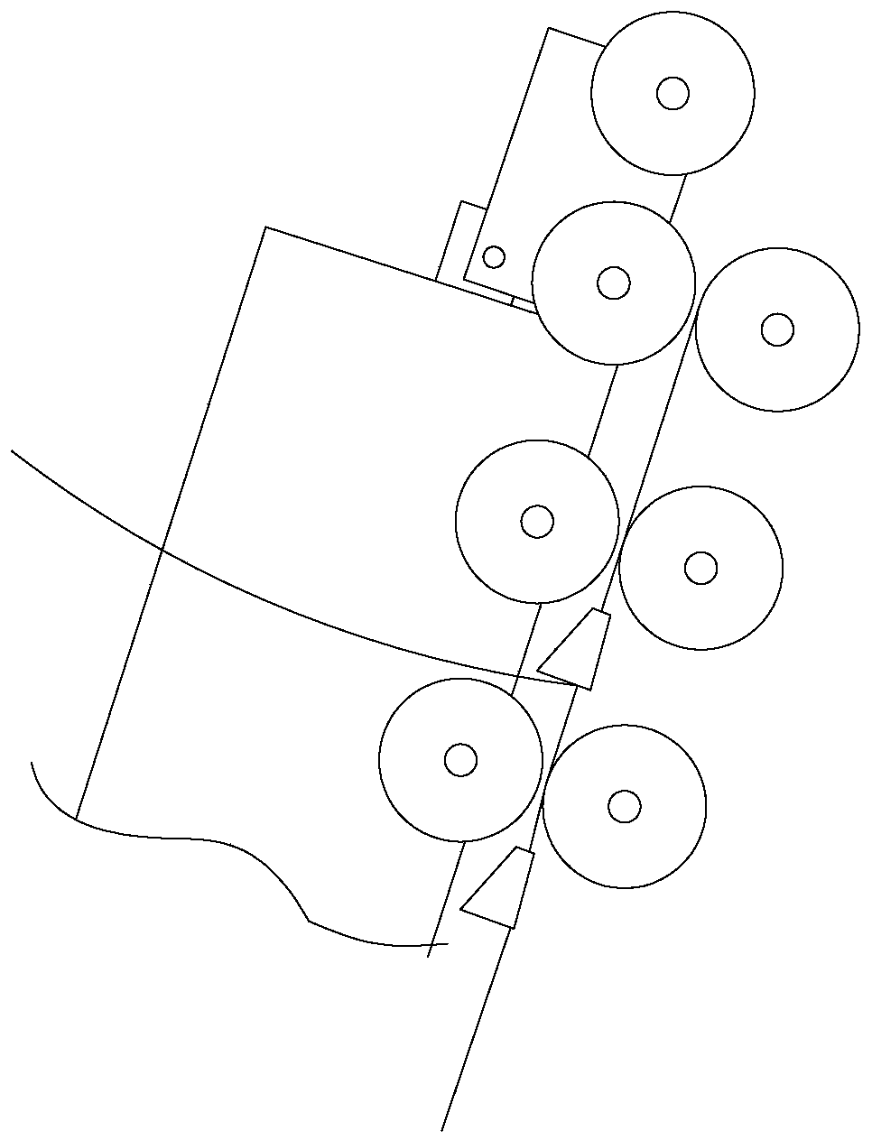
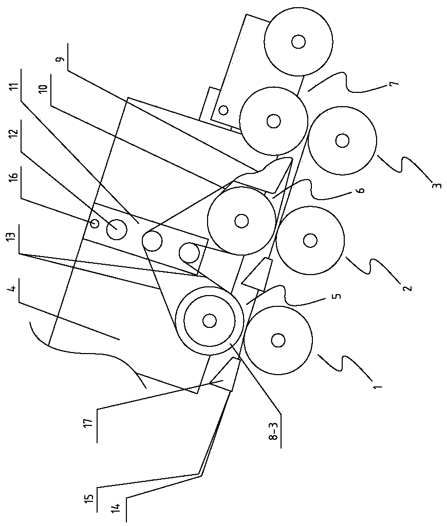
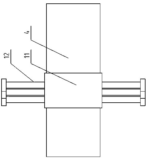
[0020] see Figure 2 to Figure 7 As shown, a special drafting spinning mechanism for spinning frame includes a rear roller 1, a middle roller 2 and a front roller 3 arranged in sequence. The rear roller 1, the middle roller 2, and the front roller 3 are driven by separate motors respectively. , The rear roller 1, the middle roller 2, the front roller 3 is provided with a cradle 4, and the cradle 4 is provided with a first top roller 5 and a second top roller 6 corresponding to the rear roller 1, the middle roller 2, and the front roller 3 respectively. , The third top roller 7, the first top roller 5 and the second top roller 6 each include a roller body 8. Both ends of the roller body 8 are provided with a large diameter section 8-1 and a small diameter section 8-2 corresponding to the width. The section 8-1 is equipped with a top roller wheel 8-3. The large-diameter section 8-1 and the small-diameter section 8-2 of the first top roller 5 and the second top roller 6 are stagge...


PUM


Abstract

The invention relates to the technical field of spinning frame equipment, in particular to a special drafting spinning mechanism for a spinning frame. The technical scheme includes that a rear roller,a middle roller and a front roller can be controlled and driven by individual motors, a cradle is arranged on upper sides of the rear roller, the middle roller and the front roller, at least one endof each roller body is provided with a large-diameter section and a small-diameter section, the widths of the large-diameter sections correspond to the widths of the small-diameter sections, the large-diameter sections and the small-diameter sections on a first upper leather roller and a second upper leather roller are correspondingly arranged in a staggered manner, the second upper leather rolleris mounted on an upper pin of the cradle in a fixedly connected manner, a first leather collar is wound on a leather roller wheel of the second upper leather roller and the upper pin, a tension frameis mounted on the cradle, at least two tensioning rods at different heights are mounted on the tension frame, one end of a second leather collar is wound on a leather roller wheel of the first upperleather roller, the other end of the second leather collar is wound on the small-diameter sections of the second upper leather roller, the middle of the second leather collar is tensioned on the two corresponding tensioning rods, and the first upper leather roller is supported by the second leather collar in a suspended manner. The special drafting spinning mechanism has the advantages that the leather collars and yarns can be conveniently accurately controlled, drafting can be effectively guaranteed, the leather collars can be prevented from slipping or dropping, and the quality of the yarnsand the spinning efficiency can be improved.

Description

Technical field [0001] The invention relates to the technical field of spinning frame equipment, in particular to a special drafting spinning mechanism for spinning frame. Background technique [0002] Spinning machine is a spinning machine that drafts, twists and winds semi-finished roving by rollers into spinning bobbins in the spinning process. In order to develop and produce special yarns such as slub yarn and segment color yarn, the current common spinning frame structure is such as figure 1 As shown, two different yarns enter from the rear roller and the middle roller respectively, and the roving is turned into a spun yarn through the rear roller and the middle roller in conjunction with the top roller. This structure has problems in the actual use process. When the production section is required When the color yarn is used, because the two kinds of yarns have to pass through the middle roller and the upper roller, when the auxiliary yarn is not needed, some auxiliary yarns...

Claims


Application Information

Patent Timeline
Patent Type & Authority Applications(China)
IPC IPC(8): D01H5/26
CPCD01H5/26
Inventor 周济恒
Owner WUXI HENGJIU ELECTRICAL TECH
Why Eureka
Try Eureka