

Large vertical shaft wind turbine achieving aerodynamic braking
An aerodynamic braking and wind turbine technology, which is applied in the direction of engine, engine function, engine control, etc., can solve the problems of vertical axis discount, increase in the cost of the whole machine, weight, etc., to enhance the structural strength and rigidity, and increase the wind cutting energy. , the effect of reducing structural costs
Inactive Publication Date: 2018-11-02
SHANGHAI WIND NEW ENERGY TECH
View PDF3 Cites 0 Cited by
- Summary
- Abstract
- Description
- Claims
- Application Information
AI Technical Summary
Problems solved by technology
1. For a horizontal axis turbine with a stand-alone power of 10MW, its blades are 80 to 100 meters long. The three-pin blade is a cantilever beam structure, and one end is fixed on the hub. Due to the dual effects of wind force and gravity, there is huge stress And the resulting deformation, its own low structural strength, easy to be damaged by strong winds, must use carbon fiber materials with higher structural strength, and the cost of materials and processes increases rapidly. The survivability is still insufficient, and damage accidents often occur in hurricanes where the blades are blown off; in addition, the unit is at a high altitude, and as the power increases, the generator becomes heavier and the height of the tower increases. The cost increases accordingly, making the cost of the whole machine rise sharply
2. If a 10MW vertical axis Darrieux turbine is used, although the blades are supported at both ends, which overcomes the shortcomings of the single-end support of the cantilever beam, the length of the main shaft is close to 100 meters. In order to ensure low shaking and rigidity during rotation, the main shaft Manufacturing costs will be much greater than horizontal axis spindles
The long main shaft with high strength and rigidity is expensive, even though the vertical axis turbine has many advantages, such as the power generation device can be placed on the ground, it is easy to install and maintain, the cost of the horizontal axis unit tower is omitted, and there is no need to yaw and face the wind, etc. Some advantages , but the cost and difficulty of the main axis still compromise the advantages of the vertical axis
3. When encountering strong winds, the braking of the turbine cannot be simply solved by the internal brake. There must be an aerodynamic brake to reduce the turbine speed to a low speed in advance, so that the internal brake can be used to stop the turbine.
Horizontal axis turbines can be aerodynamically braked by blade tip spoilers or by adjusting the pitch angle, but the aerodynamic brake problem of vertical axis turbines is difficult to solve
There is no aerodynamic braking check. Once there is a strong wind, it is very likely that a strong wind will destroy the entire turbine system. The safety of the vertical axis fan under strong wind cannot be guaranteed.
Method used
View moreImage
Smart ImageViewing Examples

Examples
Embodiment Construction
Login to View More PUM
 Abstract
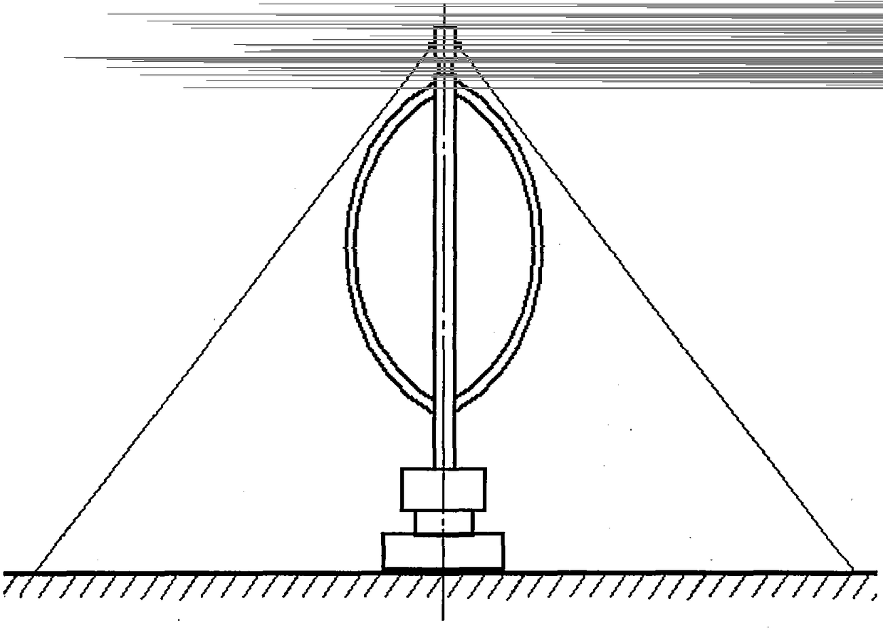
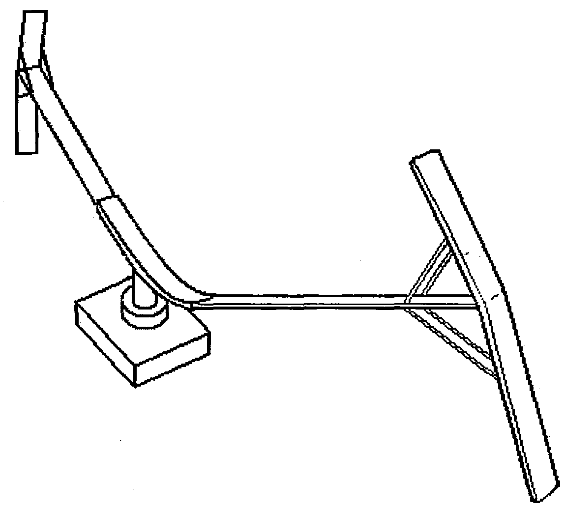
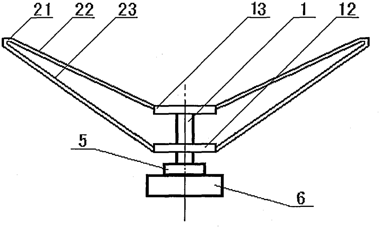
The invention discloses a variety of large compound vertical shaft wind turbine unit structures which includes a compound lift type machine composed of double-armed darrieus and an h-shaped inclined liner or a vertical liner, as well as a compound vertical shaft unit composed of lift type and resistance type wind turbine mechanism; the aerodynamic braking is realized by the reversal mechanism of the resistance type machine, the strongest structural stiffness strength in the global mainframe is achieved, so that the wind stopping speed range is improved, at the same time, the difficult problemof the aerodynamic braking is solved, wind turbine generator unit has the latest technology at home and abroad, the maximum output power and the highest degree of implementation of industrialization,and is especially suitable for offshore wind power with high single-machine power capacity.
Description
technical field The invention belongs to the technical field of turbine power generation, and specifically proposes a high-power composite vertical-axis wind turbine with an aerodynamic brake. Background technique A wind turbine (hereinafter also referred to as a wind turbine or fan for short) is a renewable energy power device that converts the kinetic energy of the wind into mechanical energy suitable for the shaft energy of the generator, and then drives the generator to rotate to generate electricity. In the whole process of wind power generation, the capacity of the turbine is the first important one. In the existing widely used horizontal-axis turbines, industry practice has proved that the increase in the power of a single machine is beneficial to reduce the cost of installed capacity per unit power and the cost of wind power generation. Therefore, the rated power capacity of a single machine continues to increase, and the single machine power of horizontal axis turb...
Claims
Login to View More Application Information
Patent Timeline
 IPC IPC(8): F03D3/06F03D3/00F03D7/06
CPCF03D3/005F03D3/061F03D3/062F03D7/06F05B2250/20F05B2250/25F05B2260/901F05B2270/602Y02B10/30Y02E10/74
Inventor 於岳亮於宙於菲
Owner SHANGHAI WIND NEW ENERGY TECH