Oil-gas separating type vacuum pump

An oil and gas separator, separation technology, applied in the direction of pumps, rotary piston type/swing piston type pump parts, pump components, etc., can solve the problems of waste materials, filter devices that cannot be cleaned, and cannot be reused, etc., to ensure The effect of adsorption efficiency

Inactive Publication Date: 2018-11-02
XIAN TECHNOLOGICAL UNIV
View PDF6 Cites 2 Cited by
  • Summary
  • Abstract
  • Description
  • Claims
  • Application Information

AI Technical Summary

Problems solved by technology

[0004] 1. The vacuum pumps in the prior art have disadvantages such as complex structure, poor heat dissipation effect and poor anti-seismic effect
[0005] 2. The general filter device cannot be cleaned, and it needs to be replaced continuously for long-term use, and it cannot be reused, which is a waste of materials, so a device is urgently needed to solve the above problems

Method used


Image

  • Oil-gas separating type vacuum pump
  • Oil-gas separating type vacuum pump
  • Oil-gas separating type vacuum pump

Examples


Embodiment Construction

[0025] The following will clearly and completely describe the technical solutions in the embodiments of the present invention with reference to the accompanying drawings in the embodiments of the present invention. Obviously, the described embodiments are only some, not all, embodiments of the present invention. Based on the embodiments of the present invention, all other embodiments obtained by persons of ordinary skill in the art without making creative efforts belong to the protection scope of the present invention.

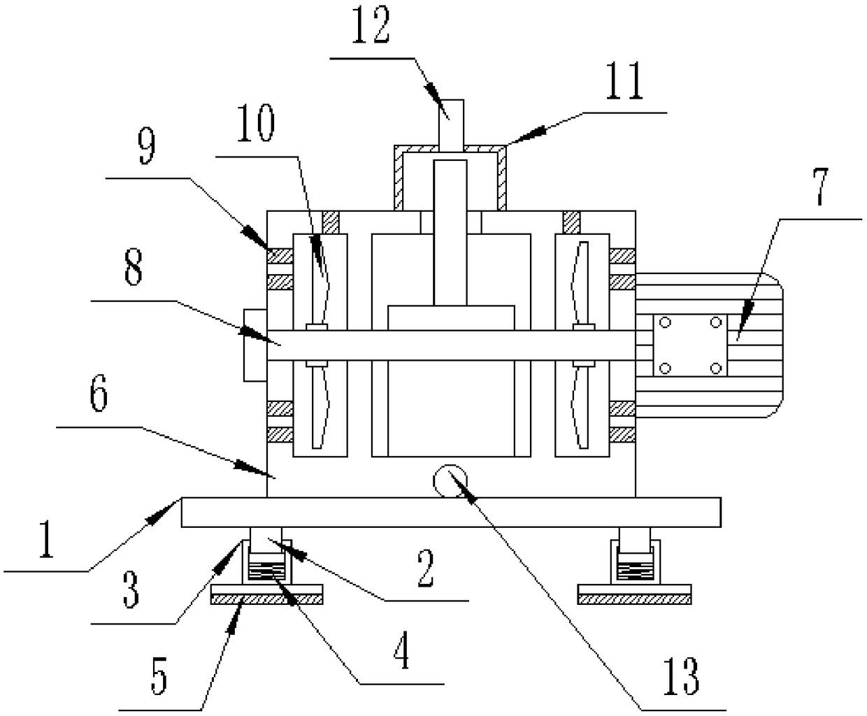
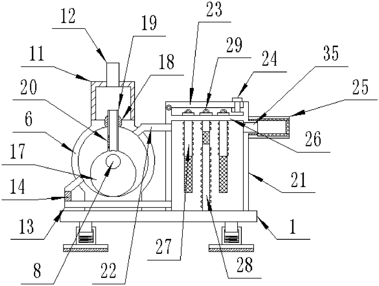
[0026] see Figure 1-6 , the present invention provides a technical solution: an oil-gas separation vacuum pump, comprising a bottom plate 1, a pump body 6 and an oil-gas separator 21, thin rods 2 are fixed vertically downward at both ends of the bottom plate 1, and the thin rods 2 The lower end is sleeved with a hollow rod 3, and the thin rod 2 slides up and down inside the hollow rod 3. The bottom end of the hollow rod 3 is fixed with a shock absorbing sprin...


PUM


Abstract

The invention discloses an oil-gas separating type vacuum pump. The oil-gas separating type vacuum pump comprises a bottom plate, a pump body and an oil-gas separator; thin rods are vertically downward and fixedly connected to the two ends of the bottom plate; hollow rods are connected to the lower ends of the thin rods in a sleeving mode; a damping spring is fixedly connected to the bottom end ofthe interior of each hollow rod; the upper ends of the damping springs are fixedly connected to the positions under the thin rods; the pump body is fixedly connected to the upper end of the bottom plate; a motor is fixedly connected to the center position of the right end of the pump body; a rotary shaft is vertically and fixedly connected to the center position of the left end of the motor; therotary shaft horizontally penetrates through the center position of the pump body; fan blades are symmetrically and fixedly connected to the upper side and the lower side of the left end of the rotaryshaft as well as the upper side and the lower side of the right end of the rotary shaft; a buffer cavity is fixedly connected to the upper end of the pump body; an air intake pipe is vertically and fixedly connected to the center position of the upper end of the buffer cavity; and a rotor is arranged inside the pump body and fixedly connected to the rotary shaft. According to the oil-gas separating type vacuum pump, a screw rod can be conveniently taken down regularly, a movable cover plate is opened, a long filter plate and a short filter plate are taken out by holding a handle, then cleaning can be carried out, the suction efficiency of a filter device is ensured, and the filter device can be recycled.

Description

technical field [0001] The invention relates to the field of mechanical equipment, in particular to an oil-gas separation vacuum pump. Background technique [0002] At present, the vacuum pump is a rotary variable displacement vacuum pump, which can be used in a wide pressure range with a large pumping speed and is insensitive to dust and water vapor in the pumped gas. Devices and vacuum pumps are widely used in plastic machinery, pesticide chemical industry, dye chemical industry, brick and tile machinery, low temperature equipment, papermaking machinery, pharmaceutical chemical industry, food machinery, industrial electric furnace, electronics industry, vacuum equipment, chemical fertilizer, metallurgy, petroleum, mining, foundation treatment In other fields, the vacuum pump needs to be lubricated by oil, and the oil-gas mixture produced after the oil evaporates will pollute the environment, so an oil-gas separation device is needed for oil-gas separation. Under the same c...

Claims


Application Information

Patent Timeline
Patent Type & Authority Applications(China)
IPC IPC(8): F04C25/02F04C29/02F04C29/04F04C29/00
CPCF04C25/02F04C29/00F04C29/0092F04C29/026F04C29/04
Inventor 来跃深来浩齐忠霞李刚
Owner XIAN TECHNOLOGICAL UNIV
Why Eureka
Try Eureka