Cylindrical roller bearing and assembling method thereof

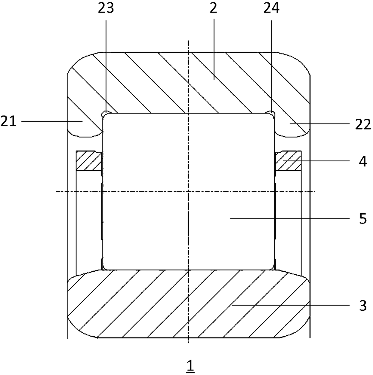
A cylindrical roller bearing and cylindrical roller technology, applied in the direction of bearing components, shafts and bearings, mechanical equipment, etc., can solve the problem of limiting the radial bearing capacity of the bearing 1, increasing the cost of raw materials and process processing, and the axial thickness of the rib. Can not be made very thin, etc., to achieve the effect of eliminating the undercut, reducing the processing cost, and increasing the axial length

Inactive Publication Date: 2018-11-02
SCHAEFFLER TECH AG & CO KG
View PDF0 Cites 2 Cited by
  • Summary
  • Abstract
  • Description
  • Claims
  • Application Information

AI Technical Summary

Problems solved by technology

However, since the bearing steel used to form the outer ring 2 is relatively brittle, in order to prevent damage to the ribs 21, 22, the axial thickness of the ribs 21, 22 cannot be made very thin
The existence of the ribs 21, 22 limits the axial space of the roller 5, thereby limiting the radial load capacity of the bearing 1, and the existence of the ribs 21, 22 increases the cost of raw materials and processing costs

Method used


Image

  • Cylindrical roller bearing and assembling method thereof
  • Cylindrical roller bearing and assembling method thereof
  • Cylindrical roller bearing and assembling method thereof

Examples


Embodiment Construction

[0029] Exemplary embodiments of the present invention are described below with reference to the accompanying drawings. It should be understood that these specific descriptions are only used to teach those skilled in the art how to implement the present invention, but are not intended to exhaust all possible ways of the present invention, nor are they intended to limit the scope of the present invention.

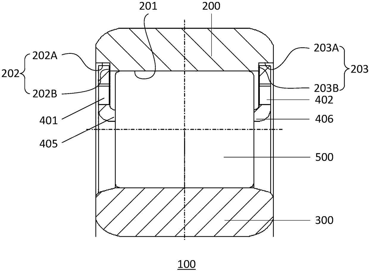
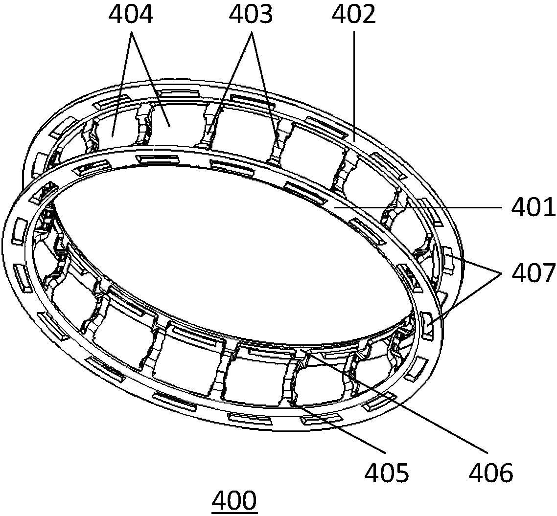
[0030] refer to Figure 2-4 , a cylindrical roller bearing (hereinafter, sometimes simply referred to as "bearing") 100 according to the present invention includes an outer ring 200, an inner ring 300, a cage 400 and a plurality of cylindrical rollers (hereinafter, sometimes simply referred to as "roller") 500 .

[0031] None on outer ring 200 figure 1 Ribs 21, 22 shown in. Two limiting grooves 202 , 203 recessed radially outward of the outer ring 200 are formed at both axial ends of the inner peripheral surface 201 of the outer ring 200 . Such as figure 2 As shown in t...


PUM


Abstract

The invention provides a cylindrical roller bearing and an assembling method thereof. The cylindrical roller bearing comprises an inner ring, an outer ring, a retainer and a plurality of cylindrical rollers; the retainer comprises two annular end surface parts and a plurality of beams which are connected to the two end surface parts, wherein limiting grooves are formed in the axial ends of the outer ring respectively; the radial outer ends of the two end surface parts are limited by the limiting grooves, so that the retainer is prevented from being separated from the outer ring; alternatively,the limiting grooves are formed in the axial ends of the inner ring respectively, the radial inner ends of the two end surface parts are limited by the limiting grooves, so that the retainer is prevented from being separated from the inner ring. According to the cylindrical roller bearing, the radial outer ends or the radial inner ends of the two end surface parts are limited by the limiting grooves, and the retainer is prevented from being separated from the outer ring or the inner ring; and flanges are not needed to arranged on the outer ring and or the inner ring, not only the axial lengthof the cylindrical roller can be increased, the radial bearing capacity of the cylindrical roller bearing is improved, and a withdraw tool groove needed for machining a roller path can be saved, andtherefore the machining cost of the outer ring or the inner ring can be reduced.

Description

technical field [0001] The invention relates to the field of bearings, more particularly to a cylindrical roller bearing and an assembly method thereof. Background technique [0002] figure 1 Shown is a NU type (double ribs on the outer ring, no ribs on the inner ring) cylindrical roller bearing according to the prior art, which is the standard structure on the market today. This cylindrical roller bearing 1 includes an outer ring 2 , an inner ring 3 , a cage 4 and a plurality of cylindrical rollers 5 . The outer ring 2 has two ribs 21, 22 with two relief grooves 23, 24 for raceway grinding relief and stress relief. [0003] This bearing does not bear axial load during operation. The two ribs 21 and 22 of the outer ring 2 are only used for axially limiting the roller 5 to prevent the roller 5 from sliding out axially. However, since the bearing steel used to form the outer ring 2 is relatively brittle, in order to prevent the ribs 21, 22 from being damaged, the axial thi...

Claims


Application Information

Patent Timeline
Patent Type & Authority Applications(China)
IPC IPC(8): F16C33/58F16C33/46F16C43/04
CPCF16C33/583F16C33/4605F16C33/4629F16C43/04
Inventor 王素霞
Owner SCHAEFFLER TECH AG & CO KG
Why Eureka
Try Eureka