Hollow decelerating device for robot
A reduction mechanism and robot technology, applied in mechanical equipment, transmission parts, gear transmission and other directions, can solve the problems of difficult installation, large volume of the reducer, poor precision, etc., to achieve low processing cost, good operation efficiency, and improved The effect of operating efficiency
- Summary
- Abstract
- Description
- Claims
- Application Information
AI Technical Summary
Problems solved by technology
Method used
Image
Examples
Embodiment 1
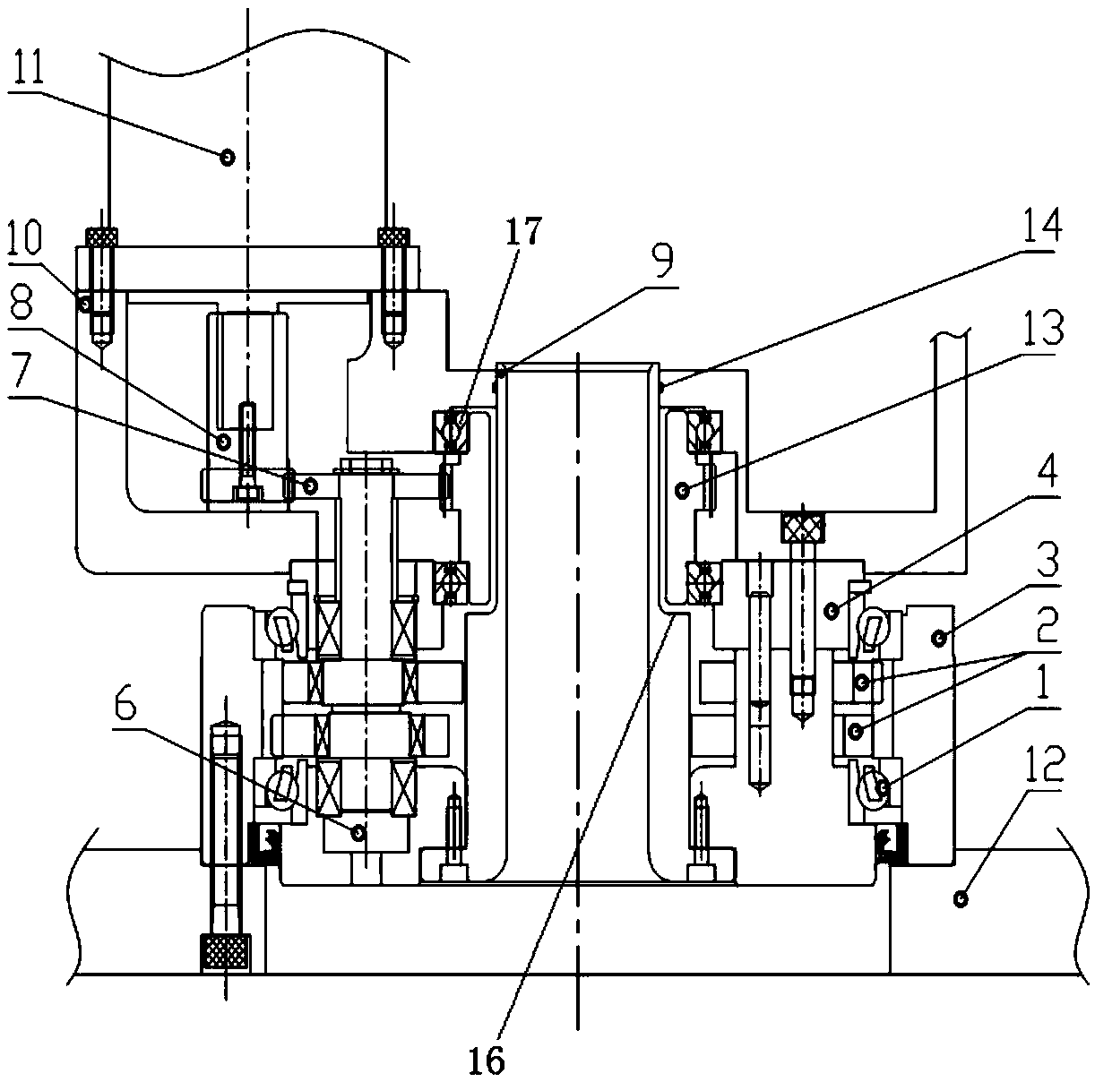
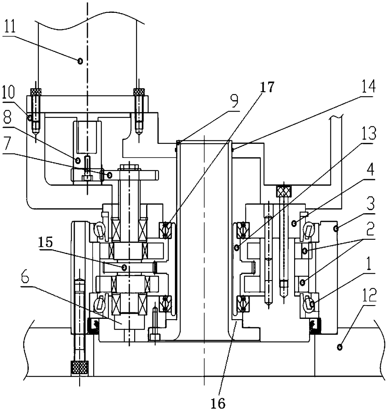
[0028] Such as figure 1 and figure 2 As shown, a hollow deceleration mechanism for a robot is characterized in that it includes a fixed end body 10, a line pipe 9 at the center, at least one set of planetary deceleration mechanisms, and at least one set of cycloidal pinwheel deceleration mechanisms; the planetary deceleration mechanism includes The input shaft 8 and the planetary gear 7 form the first-stage planetary deceleration structure; the cycloidal pin gear deceleration mechanism includes the pin gear housing 3, the cycloidal gear 2, the output frame 4, the eccentric shaft 6 and the outer edge of the cycloidal gear 2. Needle rollers, which form the second-stage cycloidal pin wheel deceleration structure; the pin gear housing 3 is located on the periphery of the cycloidal wheel 2, the output frame 4, and the eccentric shaft 6, and a pair of cycloidal wheels 2 are set on the eccentric shaft 6. Between the wire wheel 2 and the pin gear housing 3, there are a plurality of ...
Embodiment 2
[0035] Such as figure 1 and figure 2 As shown, a hollow deceleration mechanism for a robot is characterized in that it includes a fixed end body 10, a line pipe 9 at the center, at least one set of planetary deceleration mechanisms, and at least one set of cycloidal pinwheel deceleration mechanisms; the planetary deceleration mechanism includes The input shaft 8 and the planetary gear 7 form the first-stage planetary deceleration structure; the cycloidal pin gear deceleration mechanism includes the pin gear housing 3, the cycloidal gear 2, the output frame 4, the eccentric shaft 6 and the outer edge of the cycloidal gear 2. Needle rollers, which form the second-stage cycloidal pin wheel deceleration structure; the pin gear housing 3 is located on the periphery of the cycloidal wheel 2, the output frame 4, and the eccentric shaft 6, and a pair of cycloidal wheels 2 are set on the eccentric shaft 6. Between the wire wheel 2 and the pin gear housing 3, there are a plurality of ...
Embodiment 3
[0040] Such as figure 1 and figure 2 As shown, a hollow deceleration mechanism for a robot is characterized in that it includes a fixed end body 10, a line pipe 9 at the center, at least one set of planetary deceleration mechanisms, and at least one set of cycloidal pinwheel deceleration mechanisms; the planetary deceleration mechanism includes The input shaft 8 and the planetary gear 7 form the first-stage planetary deceleration structure; the cycloidal pin gear deceleration mechanism includes the pin gear housing 3, the cycloidal gear 2, the output frame 4, the eccentric shaft 6 and the outer edge of the cycloidal gear 2. Needle rollers, which form the second-stage cycloidal pin wheel deceleration structure; the pin gear housing 3 is located on the periphery of the cycloidal wheel 2, the output frame 4, and the eccentric shaft 6, and a pair of cycloidal wheels 2 are set on the eccentric shaft 6. Between the wire wheel 2 and the pin gear housing 3, there are a plurality of ...
PUM
 Abstract
Description
Claims
Application Information
 - R&D
- Intellectual Property
- Life Sciences
- Materials
- Tech Scout
- Unparalleled Data Quality
- Higher Quality Content
- 60% Fewer Hallucinations
Browse by: Latest US Patents, China's latest patents, Technical Efficacy Thesaurus, Application Domain, Technology Topic, Popular Technical Reports.
© 2025 PatSnap. All rights reserved.Legal|Privacy policy|Modern Slavery Act Transparency Statement|Sitemap|About US| Contact US: help@patsnap.com


