Bottom plate structure, air conditioning outdoor unit and air conditioning device
A technology for an air conditioner outdoor unit and an air conditioner indoor unit, which is used in air conditioning systems, space heating and ventilation, and household heating, etc., can solve the problems of low production efficiency, looseness, and many molding processes, so as to reduce molding processes and improve production. Efficiency, the effect of enhancing stability
- Summary
- Abstract
- Description
- Claims
- Application Information
AI Technical Summary
Problems solved by technology
Method used
Image

Examples
Embodiment 1
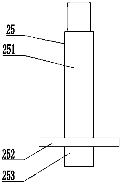
[0069] Such as figure 1 As shown, it is a schematic structural diagram of the pump foot bolt 25 of the present invention. Wherein, the pump foot bolt 25 includes a round platform 252 and an annular protrusion 253, the annular protrusion 253 is arranged at the lower end of the round platform 252, and when subjected to pressure, the annular protrusion 253 deforms, and the radial direction of the annular protrusion 253 extend.
[0070] During the molding process of the chassis, the annular protrusion 253 is inserted into the hole of the chassis, the upper mold of the chassis presses the round platform 252 and moves downward, the lower mold withstands the annular protrusion 253, and the upper mold passes through the round platform 252 to pair the annular protrusions during the downward movement. 253 is extruded to deform the annular protrusion 253, and the material around the annular protrusion 253 extends radially to it, and the annular protrusion 253 is flattened to fit the bot...
Embodiment 2
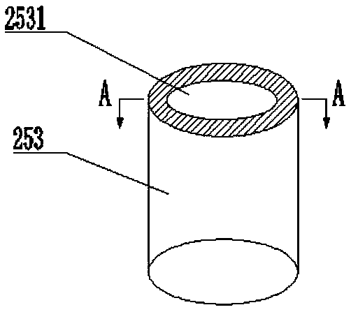
[0074] As the above-mentioned pump foot bolt 25, the difference of this embodiment is that, in combination with figure 1 As shown, the pump foot bolt 25 in this embodiment includes a bolt body 251 , a round platform 252 and an annular protrusion 253 . The round platform 252 is a solid cylinder, and the annular protrusion 253 is a hollow ring. The hollow structure of the annular protrusion 253 makes the annular protrusion 253 more likely to deform when stressed. Such as figure 2 As shown, in this embodiment, the annular protrusion 253 includes a hollow portion 2531, and the hollow portion 2531 is cylindrical, and the material around the annular protrusion 253 is evenly distributed, so that the material can extend evenly in the radial direction during the extrusion process.
[0075] The upper end of the round platform 252 is integrally formed with the lower end of the bolt body 251, and the lower end of the round platform 252 is integrally formed with the upper end of the annu...
Embodiment 3
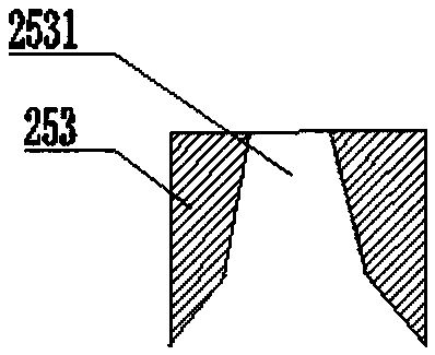
[0078] Like the pump foot bolt 25 mentioned above, the difference of this embodiment is that the annular protrusion 253 is provided with several reinforcing ribs inside, and the reinforcing ribs are integrally formed with the inner wall of the hollow part 2531 . During the extrusion process, the reinforcing rib can prevent the annular protrusion 253 from extending radially inward after being compressed. The reinforcing ribs are evenly distributed inside the annular protrusion 253, and the two are parallel to each other. The plane where the reinforcing ribs are located is perpendicular to the cross section of the annular protrusion 253. This arrangement can ensure the use of a small number of reinforcing ribs and can fully exert the anti-circular effect of the reinforcing ribs. The function of the protrusion 253 extending radially inward after being compressed. In this way, the material is saved, and the forming effect between the pump foot bolt 25 and the chassis is ensured. ...
PUM
 Abstract
Description
Claims
Application Information
 - Generate Ideas
- Intellectual Property
- Life Sciences
- Materials
- Tech Scout
- Unparalleled Data Quality
- Higher Quality Content
- 60% Fewer Hallucinations
Browse by: Latest US Patents, China's latest patents, Technical Efficacy Thesaurus, Application Domain, Technology Topic, Popular Technical Reports.
© 2025 PatSnap. All rights reserved.Legal|Privacy policy|Modern Slavery Act Transparency Statement|Sitemap|About US| Contact US: help@patsnap.com