Medical breathing carbon dioxide measurement system

A technology of carbon dioxide and gas to be measured, applied in the medical field, can solve the problems of inconvenient application, increased measurement error due to the difference of dual channels, etc., and achieves the effect of improving stability and saving cost.

Pending Publication Date: 2018-11-02
SHENZHEN UNIV
View PDF8 Cites 1 Cited by
  • Summary
  • Abstract
  • Description
  • Claims
  • Application Information

AI Technical Summary

Problems solved by technology

[0004] At present, medical respiratory carbon dioxide detection requires two detectors to form two signal amplification channels, which doubles the cost, a...

Method used


Image

  • Medical breathing carbon dioxide measurement system
  • Medical breathing carbon dioxide measurement system
  • Medical breathing carbon dioxide measurement system

Examples


Embodiment 1

[0023] This application is used to provide a medical breath carbon dioxide detection system, which provides hardware support for the measurement of medical breath carbon dioxide. By installing corresponding software on the system of the present application, the carbon dioxide produced by respiration can be measured.

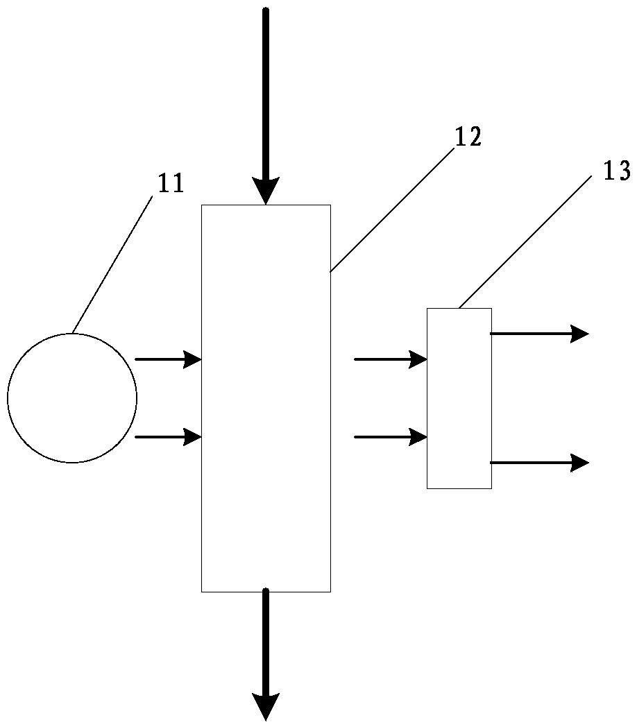
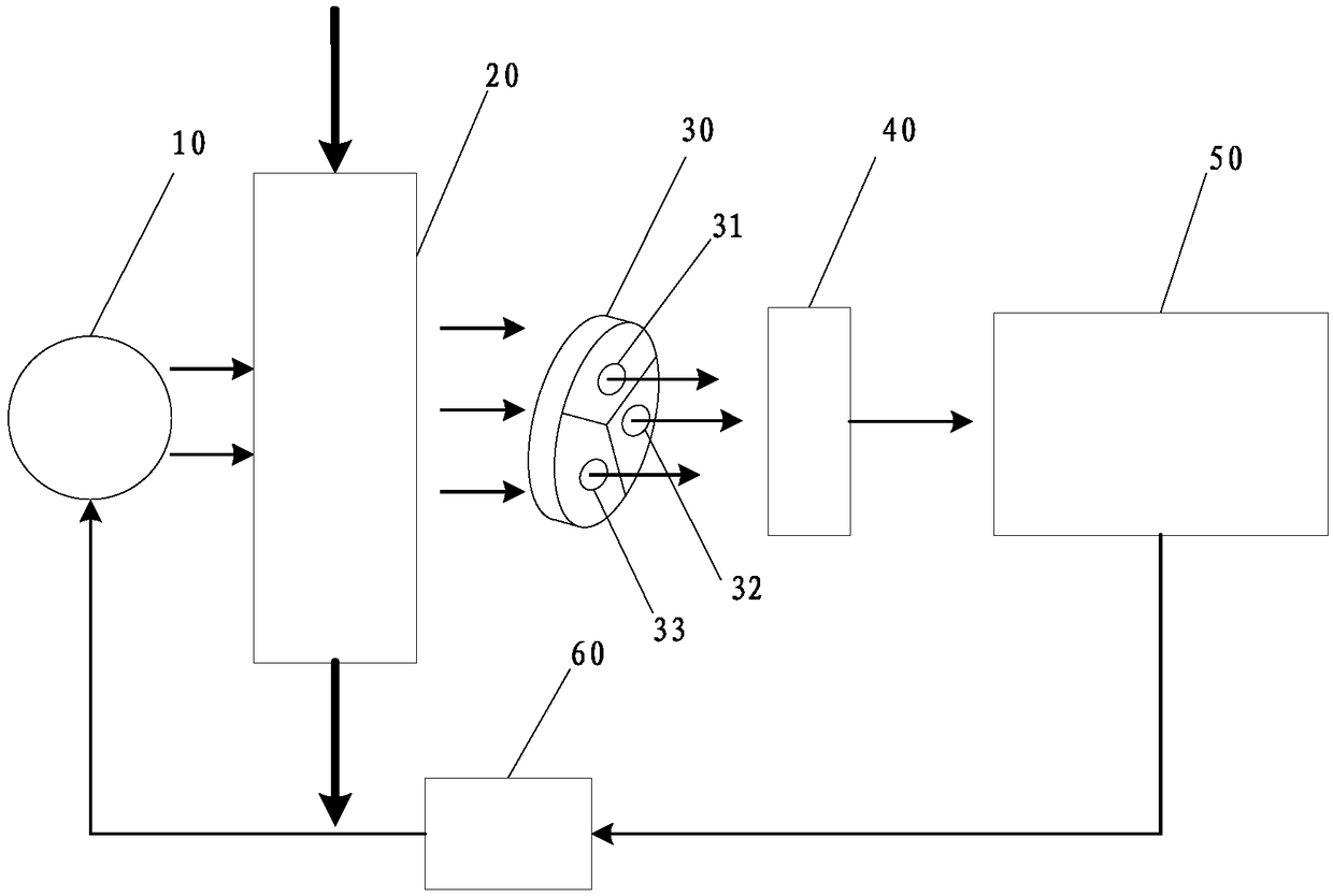
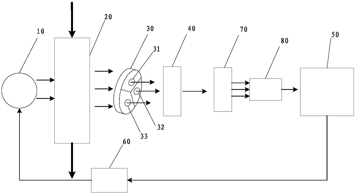
[0024] Such as figure 2 , image 3 As shown, a medical breathing carbon dioxide detection system includes a light source 10, an air chamber 20, a chopper wheel 30, a motor (not shown), a detector 40, a processor 50 and a light source driving circuit 60, and the air chamber 20 is used for Through the gas to be measured, the light source 10 is used to irradiate the gas chamber 20 to form an optical path, and the motor is used to drive the chopper wheel 30. The chopper wheel 30 is provided with multiple measurement windows, and the chopper wheel 30 is arranged on the optical path. , the single optical path is divided into multiple measurement channels, there are ...

Embodiment 2

[0031] Figure 4 It is a flow chart of the method for obtaining medical respiratory carbon dioxide concentration provided by Embodiment 2 of the present invention. The execution subject of this embodiment may be a computer device or a functional unit in the computer device, including the following steps:

[0032] Step 102: setting three measurement windows on the chopper wheel, and sealing a carbon dioxide standard gas of known concentration in one of the measurement windows.

[0033] Three measurement windows are set on the chopper wheel, which can be realized specifically by setting three through holes on the chopper wheel and setting transparent covers at both ends of the through holes. In one embodiment, considering the consistency of the optical path, the measurement windows are all hollow cylinders arranged on the chopper wheel and transparent covers are provided at both ends to ensure the symmetry of the optical path and ensure the three The light path of the path is c...


PUM


Abstract

A medical breathing carbon dioxide detection system comprises light source and an air chamber, the air chamber is used for gas (to be measured) to pass through, and the light source is used for illuminating the air chamber to form an optical path. And further comprises a chopping wheel disk, a motor, a detector and a processor, the chopping wheel disk is provided with a plurality of measurement windows, one of which is used for encapsulating the standard gas with known concentration, the motor is used for driving the chopping wheel disk which is arranged on the optical path, the single opticalpath is divided into a plurality of measurement channels; the detector is used for acquiring the signal on the measurement channels and sending the signal to the processor for processing; the processor is also used for controlling the light source. Due to a plurality of measurement channels require only one detector, the cost is reduced, when performing zero point correction, the standard gas with known concentration is accorded with without the introduction of external air as the zero reference point, the impact of the zero deviation caused by external zero reference gas on the measurementis avoided, the operation free of zero correction function is realized, and the stability of the measurement is improved.

Description

technical field [0001] The present application relates to the medical field, in particular to a medical breathing carbon dioxide detection system. Background technique [0002] Medical respiratory carbon dioxide monitoring is one of the key parameters in modern clinical operations and intensive care. It can be applied to multi-parameter respiratory gas monitors, ventilators, anesthesia machines and special monitors for breathing gas. Among them, the medical respiratory heart carbon dioxide monitoring technology is Among them, the key core technology, the medical respiratory carbon dioxide measurement technology currently used in the above-mentioned system usually adopts the technology of infrared spectrum absorption, and there are side-stream and mainstream implementation methods, all of which need to carry out zero-reference input zero-calibration operation to achieve accurate Measurement. [0003] At present, common medical carbon dioxide gas measurement systems, such as ...

Claims


Application Information

Patent Timeline
IPC IPC(8): G01N21/84G01N21/01
CPCG01N21/01G01N21/84
Inventor 叶继伦叶南亭刘春生宋学东张旭
Owner SHENZHEN UNIV
Why Eureka
Try Eureka