Adjustable solar silicon wafer storage equipment
A technology of solar silicon wafers and storage devices, applied in the direction of climate sustainability, sustainable manufacturing/processing, photovoltaic power generation, etc., can solve the problems of inability to move up and down, single function, etc., achieve simple structure, reduce labor intensity, and produce low cost effect
- Summary
- Abstract
- Description
- Claims
- Application Information
AI Technical Summary
Problems solved by technology
Method used
Image

Examples
Embodiment 1
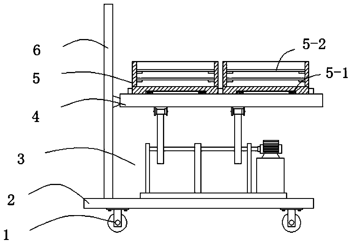
[0023] Such as Figures 1 to 2 As shown, this embodiment provides an adjustable solar silicon wafer storage device, which includes a bottom support plate 2, and is characterized in that a vertical guide plate 6 is provided on one side of the bottom support plate 2, and a vertical guide plate 6 is provided above the bottom support plate 2. A horizontal placement mechanism 4 that moves up and down along the vertical guide plate 6. The horizontal placement mechanism 4 is provided with a plurality of storage areas 4-1, and the storage area 4-1 is provided with a composite storage box 5 for loading solar silicon wafers. , the bottom support plate 2 is provided with a composite drive mechanism 3 composite storage box 5 that drives the horizontal placement mechanism 4 up and down.
[0024] The storage area 4-1 is provided with a positioning protruding ring 4-1.1, and the lower surface of the bottom of the composite storage box 5 is provided with a center groove 5-1 that cooperates wi...
Embodiment 2
[0027] This embodiment is further optimized on the basis of embodiment 1, specifically:
[0028] A plurality of placement boards 5-2 are detachably arranged in the composite storage box 5 .
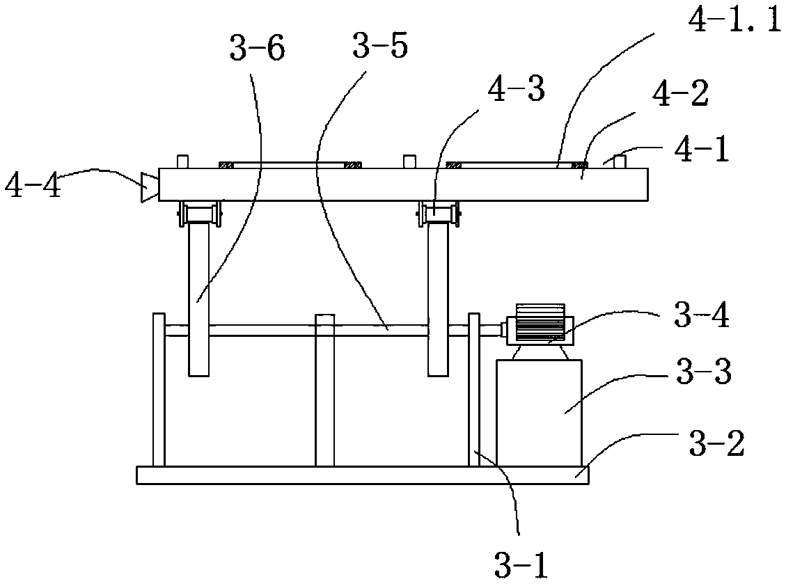
[0029] The horizontal placement mechanism 4 includes a horizontal plate 4-2, on which a guide block 4-4 cooperating with the vertical guide plate 6 is arranged.
[0030] The compound driving mechanism 3 is a combined eccentric wheel lifting mechanism, and the combined eccentric wheel lifting mechanism includes a rotating shaft 3-5, a base plate 3-2 fixed on the bottom support plate 2, and a base plate 3-2 on the base plate 3-2. Three supporting plates 3-1 for supporting the rotating shaft 3-5 are arranged at equal intervals, and an eccentric wheel 3-6 and a horizontal plate 4 are arranged on the rotating shaft 3-5 between two adjacent supporting plates 3-1. A contact wheel 4-3 that cooperates with the eccentric wheel 3-6 is arranged below the -2.
[0031] One end of the rotating shaft 3...
Embodiment 3
[0033] This embodiment is further optimized on the basis of embodiment 1, specifically:
[0034] The contact wheel 4-3 is a different-diameter wheel whose middle diameter is smaller than that of both ends, and the width of the middle small diameter part of the contact wheel 4-3 is 0.5-1 mm larger than the width of the eccentric wheel 3-6.
[0035] A plurality of mobile roller mechanisms 1 with brake mechanisms are arranged under the bottom support plate 2 .
PUM
 Abstract
Description
Claims
Application Information
 - R&D Engineer
- R&D Manager
- IP Professional
- Industry Leading Data Capabilities
- Powerful AI technology
- Patent DNA Extraction
Browse by: Latest US Patents, China's latest patents, Technical Efficacy Thesaurus, Application Domain, Technology Topic.
© 2024 PatSnap. All rights reserved.Legal|Privacy policy|Modern Slavery Act Transparency Statement|Sitemap