
A method for fixing and welding high-speed steel bars for cutting tools

A welding method and high-speed steel technology, applied in welding equipment, manufacturing tools, metal processing equipment, etc., can solve the inconsistency of tool quality, performance stability and uniformity, tool stability and uniformity, and multiple tool processing steps and other problems, to achieve the effect of reducing the preparation process, good welding effect and improving efficiency

Active Publication Date: 2020-07-03
DONGE LIYUAN MACHINERY KNIFE
View PDF7 Cites 0 Cited by
  • Summary
  • Abstract
  • Description
  • Claims
  • Application Information

AI Technical Summary

Problems solved by technology

[0005] (1) In the process of tool processing, the raw materials are cut into blanks one by one for processing. Each blank is an independent product to be processed. The processing is cumbersome, the efficiency is difficult to improve, and the production cost is high.
[0006] (2) There are many tool processing steps, and the stability and uniformity of the tool performance are inconsistent during the processing process. Different operators and different equipment will have differences. At the same time, there will be a reject rate during the processing process. The main factors that affect the quality are the welding process, especially for tools with larger cross-sections. Due to the amount of solder used during the welding process, the quality of the solder itself, the stability of the substrate and high-speed steel bars during the welding process, etc. The result of welding is affected by
[0007] (3) The post-welding treatment process is performed on the welded blanks one by one. There are also problems such as cumbersome processing, difficulty in improving production costs, and high production costs. The tool quality, performance stability, and uniformity are not consistent. The problem

Method used


Image

  • A method for fixing and welding high-speed steel bars for cutting tools
  • A method for fixing and welding high-speed steel bars for cutting tools
  • A method for fixing and welding high-speed steel bars for cutting tools

Examples


Embodiment Construction

[0039] Below in conjunction with embodiment, further illustrate the present invention.

[0040] see Figure 5 , Figure 6 As can be seen, in the cutting tool machining process of the prior art, the blade portion hardness of cutting is high, is generally by making groove platform 6 on the blank 5 of the steel material of making cutter body, on groove platform 6, lays solder powder, solder layer 7, After the high-speed steel bar 4, the blank 5 and the high-speed steel bar 4 are fixed by a clamp, and the high-speed steel bar 4 is welded.

[0041] The processing of the existing technology is cumbersome, the efficiency is difficult to improve, and the production cost is high. It uses solder powder and solder, which has low welding efficiency and affects the quality of the tool. At the same time, the subsequent processing cost after welding is also high. A detailed description.

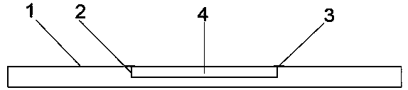
[0042] see Figure 1-Figure 4 As can be seen, the fixing, welding method of a kind of cutter high-sp...


PUM

PropertyMeasurementUnit
heightaaaaaaaaaa
widthaaaaaaaaaa

Abstract

The invention discloses a cutter high-speed steel rod fixing and welding method. The method comprises the following steps that (1) a substrate is prepared, specifically, a cold drawing technology is adopted, the substrate is produced, the overall width of the substrate is equal to the sum of two cutter body widths and the cutting and polishing loss width, the center of the substrate is provided with an embedded groove, the depth of the embedded groove is equal to the thickness of a high-speed steel rod, and the edge of the embedded groove is provided with fixing ribs extending towards the upper portion of the substrate; (2) the substrate is cleaned; (3) the high-speed steel rod is embedded, specifically, the high-speed steel rod is embedded in the embedded groove, the fixing ribs are rolled, the high-speed steel rod is closely attached to the substrate through the fixing ribs, and a long blank with the high-speed steel rod is obtained; and (4) welding is conducted, specifically, the long blank with the high-speed steel rod is welded. According to the technology, the machining steps are decreased, the machining process is shortened, the machining difficulty is lowered, the machiningefficiency is improved, the machining cost is reduced, and the machining yield, the machining quality and the performance stability are improved.

Description

technical field [0001] The invention relates to a tool processing method, in particular to a method for fixing and welding a tool high-speed steel bar. Background technique [0002] During tool processing, the cutting edge has high hardness. Generally, a slot table is made on the steel substrate of the cutter body, and high-speed steel bars are laid and welded on the slot table. [0003] The specific process of the above-mentioned tool processing includes the following steps: blanking - punching - straight blank - planing table - cleaning - welding - tempering (multiple tempering according to needs, generally 2-3 times) - straightening - grinding Face - milling one side - fine grinding width - fine grinding length - planer edge - straightening - fine grinding edge - cleaning, rust prevention, finished product packaging. [0004] Above-mentioned processing has the following technical problems: [0005] (1) In the tool processing process, the raw materials are cut into blank...

Claims


Application Information

Patent Timeline
Patent Type & Authority Patents(China)
IPC IPC(8): B23K31/02B23P15/28
CPCB23K31/02B23P15/28
Inventor 许纪刚
Owner DONGE LIYUAN MACHINERY KNIFE
Learn More