Electromechanical cylindrical short tube derusting device

A technology of cylindrical and short tubes, which is applied in the field of electromechanical cylindrical short tube derusting devices, which can solve the problems of easily injured hands, easy residual impurities in short tubes, time-consuming and labor-intensive problems, etc.

Active Publication Date: 2018-11-06
滨州高新区国有资本投资运营有限公司
View PDF8 Cites 7 Cited by
  • Summary
  • Abstract
  • Description
  • Claims
  • Application Information

AI Technical Summary

Problems solved by technology

[0004] In order to overcome the disadvantages of manually derusting the short pipe, it is time-consuming and laborious, the hands are easily injured during derusting, and impurities are easy to remain on the short pipe after derusting, the technical pro

Method used


Image

  • Electromechanical cylindrical short tube derusting device
  • Electromechanical cylindrical short tube derusting device
  • Electromechanical cylindrical short tube derusting device

Examples


Embodiment 1

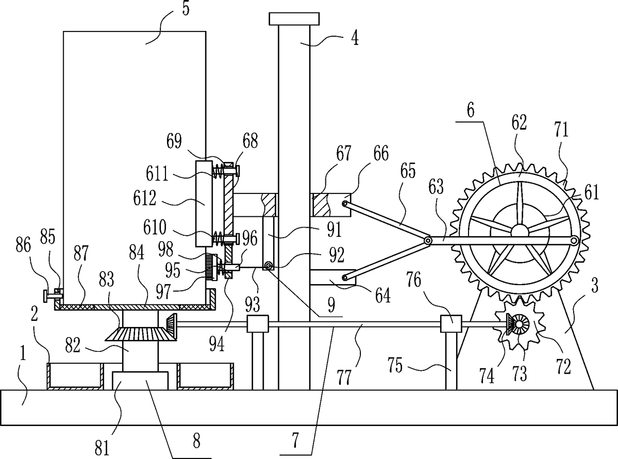
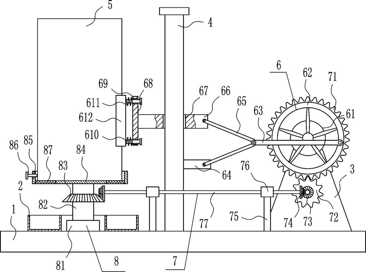
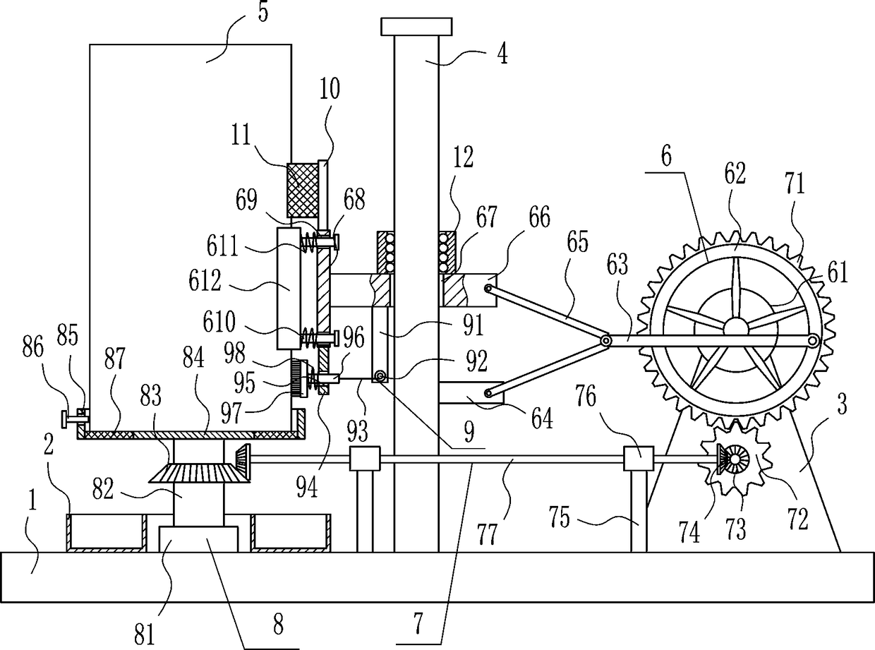
[0026] A kind of electromechanical cylindrical short tube derusting device, such as Figure 1-3 As shown, it includes a bottom plate 1, an annular frame 2, a support seat 3, a vertical rod 4, a derusting device 6, a transmission device 7 and a fixing device 8, a vertical rod 4 is installed in the middle of the top of the bottom plate 1, and a Support base 3, a derusting device 6 is provided between the top of the support base 3 and the vertical bar 4, a transmission device 7 is provided in the middle of the top of the bottom plate 1, the transmission device 7 is connected with the derusting device 6, and a fixing device is provided on the left side of the top of the bottom plate 1 8. The fixing device 8 is located at the bottom left of the derusting device 6, and the ring frame 2 is installed on the left side of the top of the bottom plate 1, and the fixing device 8 is located at the center of the ring frame 2.

Embodiment 2

[0028] A kind of electromechanical cylindrical short tube derusting device, such as Figure 1-3 As shown, it includes a bottom plate 1, an annular frame 2, a support seat 3, a vertical rod 4, a derusting device 6, a transmission device 7 and a fixing device 8, a vertical rod 4 is installed in the middle of the top of the bottom plate 1, and a Support base 3, a derusting device 6 is provided between the top of the support base 3 and the vertical bar 4, a transmission device 7 is provided in the middle of the top of the bottom plate 1, the transmission device 7 is connected with the derusting device 6, and a fixing device is provided on the left side of the top of the bottom plate 1 8. The fixing device 8 is located at the bottom left of the derusting device 6, and the ring frame 2 is installed on the left side of the top of the bottom plate 1, and the fixing device 8 is located at the center of the ring frame 2.

[0029] The derusting device 6 includes a motor 61, a rotating di...

Embodiment 3

[0031] A kind of electromechanical cylindrical short tube derusting device, such as Figure 1-3 As shown, it includes a bottom plate 1, an annular frame 2, a support seat 3, a vertical rod 4, a derusting device 6, a transmission device 7 and a fixing device 8, a vertical rod 4 is installed in the middle of the top of the bottom plate 1, and a Support base 3, a derusting device 6 is provided between the top of the support base 3 and the vertical bar 4, a transmission device 7 is provided in the middle of the top of the bottom plate 1, the transmission device 7 is connected with the derusting device 6, and a fixing device is provided on the left side of the top of the bottom plate 1 8. The fixing device 8 is located at the bottom left of the derusting device 6, and the ring frame 2 is installed on the left side of the top of the bottom plate 1, and the fixing device 8 is located at the center of the ring frame 2.

[0032] The derusting device 6 includes a motor 61, a rotating di...


PUM


Abstract

The invention relates to a derusting device, in particular to an electromechanical cylindrical short tube derusting device, and aims to solve the technical problem of providing the electromechanical cylindrical short tube derusting device which saves time and labor, does not need manual derusting, is unlikely to hurt a hand and can brush and remove impurities on a short tube. According to the technical scheme, electromechanical cylindrical short tube derusting device comprises a bottom plate and the like, wherein a vertical rod is mounted in the middle of the top of the bottom plate; a supportseat is mounted on the right side of the top of the bottom plate; a derusting device body is arranged between the top of the support seat and the vertical rod; a transmission device is arranged in the middle of the top of the bottom plate and is connected with the derusting device body; and a fixed device is arranged on the left side of the top of the bottom plate and is positioned at the lower left part of the derusting device body. According to the electromechanical cylindrical short tube derusting device, a brushing and removing device is adopted to brush and remove impurities rest on theshort tube; and an annular frame is adopted to collect fallen scrap iron to prevent the scrap iron from falling on the ground to affect the surrounding environment, so that the effects that time and labor are saved, manual derusting is not needed, and the hand is unlikely to hurt are realized.

Description

technical field [0001] The invention relates to a rust removal device, in particular to an electromechanical cylindrical short tube rust removal device. Background technique [0002] Mechanical and electrical products refer to all kinds of agricultural machinery, electrical appliances, and electronic performance production equipment and household tools produced by machinery, electrical appliances, and electronic equipment. Generally include mechanical equipment, electrical equipment, means of transportation, electronic products, electrical products, instruments and meters, metal products, etc. and their parts and components. [0003] If the short tube is placed for a long time, it is prone to rust, and the short tube needs to be derusted before it can be used better. When manually derusting the short tube, it is time-consuming and laborious, and the hands are easily injured during derusting. Impurities are easy to remain on the short tube, so it is urgent to develop an elec...

Claims


Application Information

Patent Timeline
IPC IPC(8): B24B27/033B24B29/00B24B55/12
CPCB24B27/033B24B29/005B24B55/12
Inventor 王斌
Owner 滨州高新区国有资本投资运营有限公司
Why Eureka
Try Eureka