Steel shot rust removing device

A technology of steel shot and rust remover, which is applied to grinding machines, surface polishing machine tools, metal processing equipment, etc., can solve the problems of large mechanical wear, high use cost, affecting production efficiency, etc., so as to reduce damage and improve production efficiency. , The effect of low mechanical maintenance cost

Inactive Publication Date: 2018-02-09
郑行良
View PDF0 Cites 1 Cited by
  • Summary
  • Abstract
  • Description
  • Claims
  • Application Information

AI Technical Summary

Problems solved by technology

[0004] At present, in the production of steel shot, molten steel is centrifugally thrown into water to form steel shot, and the steel shot needs to be heated and dried to remove moisture, but at the same time, oxide skin is formed on the surface of the steel shot, causing corrosion on the surface of the steel shot and affecting the steel shot. The surface quality, the shot blasting effect of the steel shot becomes worse
The traditional method of removing scale is to use equipment such as a rice mill to remove the scale on the surface of the steel shot by mutual rolling of convex teeth and grooves, which has low production efficiency and poor rust removal effect
[0005] Even if the steel shot is derusted by rolling, the device needs a practical material with high wear resistance, and the steel shot will wear a lot on the machine. When the wear reaches a certain level, the whole machine needs to be replaced, which leads to high use cost and affects the Productivity

Method used


Image

  • Steel shot rust removing device
  • Steel shot rust removing device
  • Steel shot rust removing device

Examples


Embodiment Construction

[0021] The present invention will be further described below in conjunction with accompanying drawing:

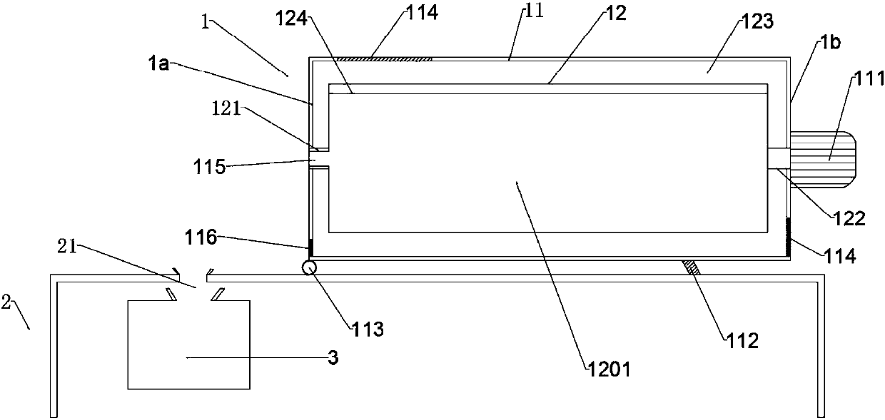
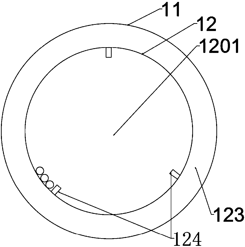
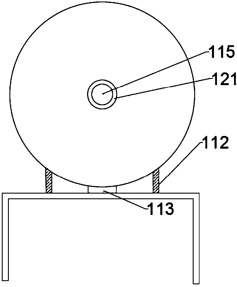
[0022] Such as Figure 1-4 As shown, the derusting machine 1 is composed of a cylindrical rolling outer shell 11 and a rolling inner shell 12, and the rolling inner shell 12 is arranged in the rolling outer shell 11. The two top surfaces of the rolling shell 11 are respectively the first side cover 1a and the second side cover 1b, the first side cover 1a is provided with a material opening 115 and a waste material opening 116, and the second side cover 1b is provided with a rotating motor 111 and an observation port 114 . The rolling inner shell 12 and the rolling outer shell 11 are connected through the first rotating shaft 121 and the second rotating shaft 122. Turn the motor 111.

[0023] The inside of the rolling inner shell 12 is a derusting bin 1201, and the first rotating shaft 121 is a central structure. The derusting bin 1201 communicates with the external space...


PUM


Abstract

The invention discloses a steel shot derusting device, belonging to the field of steel shot production, comprising a derusting machine and a base; the derusting machine is composed of a rolling outer shell and a rolling inner shell; The first side of the rolling shell is provided with a material port; the lower part of the rolling shell is provided with a waste port, a movable pin and a supporting device; the rolling inner shell is arranged inside the rolling shell, and the space between the two forms a spacer layer; The second rotating shaft is connected with the first rotating shaft; the first rotating shaft is a central structure, the first rotating shaft communicates with the discharge port, and the derusting bin communicates with the outside world through the first rotating shaft as the central part; the rotating motor passes through the second The rotating shaft rotates and rolls the inner shell; the beneficial effect is: using the friction and derusting of the steel shot itself, the surface of the steel shot can be fully derusted, and the damage to the surface of the steel shot is reduced; the rust and the steel shot are better separated; Replaceable derusting chamber, low cost of mechanical maintenance; improved production efficiency.

Description

technical field [0001] The invention belongs to the field of steel shot production, in particular to a steel shot derusting device. Background technique [0002] Steel shot is a commonly used surface treatment material. There are many types of steel shot. For different types of steel shot, the raw materials and equipment required are also different. [0003] Steel shot is a high-quality wear-resistant material. Steel shot has moderate hardness, strong toughness, good impact resistance and long service life. It has good resilience, fast cleaning speed and low consumption when cleaning workpieces. Steel shots are used in a wide range of fields, such as castings, forgings, surface treatment of parts after machining, and surface treatment of parts after heat treatment. Steel shots are used in many fields. [0004] At present, in the production of steel shot, molten steel is centrifugally thrown into water to form steel shot, and the steel shot needs to be heated and dried to ...

Claims


Application Information

Patent Timeline
Patent Type & Authority Applications(China)
IPC IPC(8): B24B31/02
CPCB24B31/02
Inventor 郑行良
Owner 郑行良
Why Eureka
Try Eureka