Vehicle stopping device for new energy vehicle

A technology of new energy vehicles and blocks, which is applied to vehicle components, transportation and packaging, brakes, etc., can solve the problems of increasing the working intensity of the staff, inconvenient handling of blocks, and easy accidents, so as to improve the anti-skid coefficient, The effect of improving stability and reducing work intensity

Active Publication Date: 2018-11-06
齐河智谷产业发展有限公司
View PDF6 Cites 1 Cited by
  • Summary
  • Abstract
  • Description
  • Claims
  • Application Information

AI Technical Summary

Problems solved by technology

Then such a new energy vehicle power source also has a shortcoming, that is, when the new energy vehicle is installed, debugged and maintained, due to factors such as accidentally turning on the power supply, the car may start without precautions, so there is a great safety hazard. Hidden danger
Therefore, it is necessary to place a block in front of the tires of the car before the inspection and maintenance of the new energy vehicle. In order to prevent the block from slipping easily or the wheel from crossing the block, the block is usually set to be large and cumbersome, so it is extremely difficult to carry the block It is convenient and increases the working intensity of the staff, and if the staff has not completely exited, the car has already started power-on inspection, which is likely to cause accidents

Method used


Image

  • Vehicle stopping device for new energy vehicle
  • Vehicle stopping device for new energy vehicle
  • Vehicle stopping device for new energy vehicle

Examples


Embodiment Construction

[0020] The following will clearly and completely describe the technical solutions in the embodiments of the present invention with reference to the accompanying drawings in the embodiments of the present invention. Obviously, the described embodiments are only some, not all, embodiments of the present invention. Based on the embodiments of the present invention, all other embodiments obtained by persons of ordinary skill in the art without making creative efforts belong to the protection scope of the present invention.

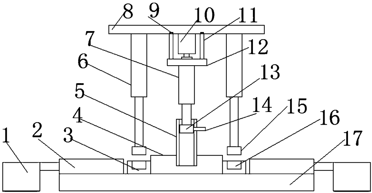
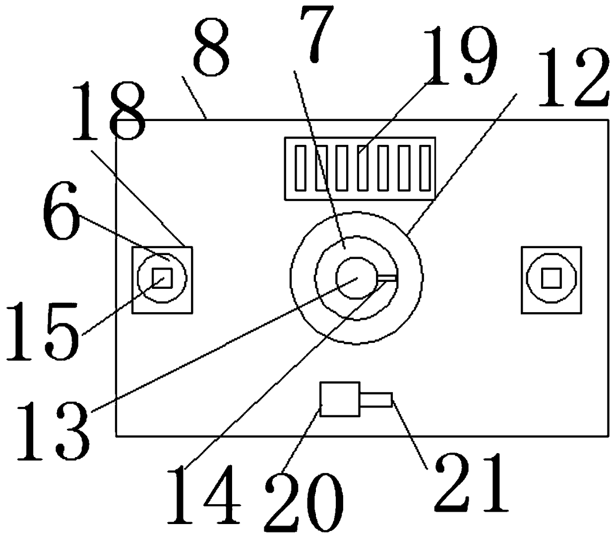
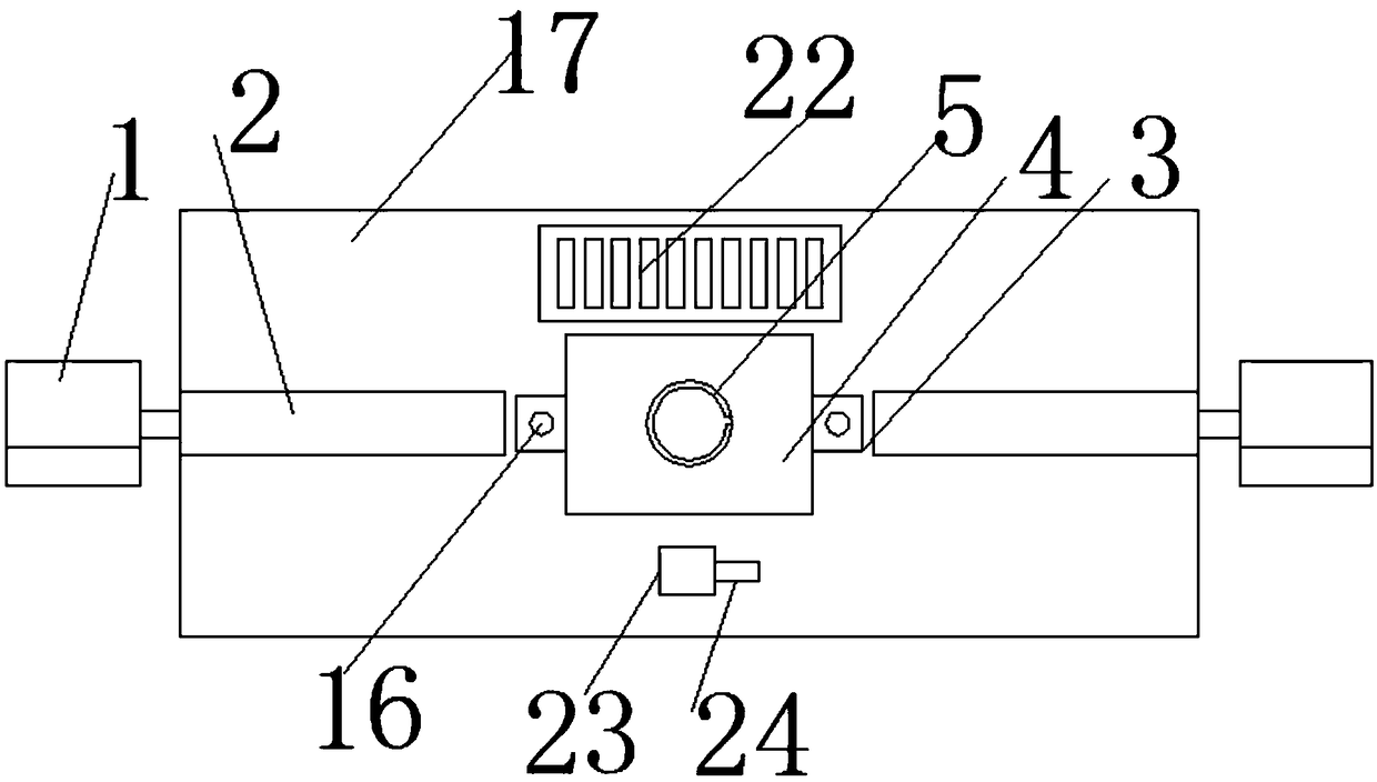
[0021] see Figure 1-7 , in an embodiment of the present invention, a car stop device for new energy vehicles, including a block 1, a first hydraulic cylinder 2, an iron block 3, a fixed platform 4, a connecting pipe 5, a second hydraulic cylinder 6, a third hydraulic Cylinder 7, mounting plate 8, guide rail 9, motor 10, connecting rod 11, rotating plate 12, clamping block 13, clamping rod 14, magnet 15, clamping groove 16, fixing plate 17, fixing seat 18, fir...


PUM


Abstract

The invention discloses a vehicle stopping device for a new energy vehicle, comprising stoppers, first hydraulic cylinders, iron blocks, a fixing table, a connecting pipe, second hydraulic cylinders,a third hydraulic cylinder, a mounting plate, guide rails, a motor, connecting rods, a rotating plate, a clamping block, a clamping rod, a magnet, a clamping groove, a fixing plate, fixing seats and afirst battery. The third hydraulic cylinder is used for controlling the clamping block and the clamping rod to rise or fall, thereby controlling the connecting pipe to rise or fall, so that the fixing plate is controlled to rise or fall to the ground, and the rotating plate is driven by the motor to rotate so as to control the third hydraulic cylinder to rotate, the third hydraulic cylinder rotates and the third hydraulic cylinder controls the clamping block, so that the clamping block and the clamping rod are controlled to extend into or be disengaged from a fixing groove, and the second hydraulic cylinder is used for controlling the magnet to rise or fall. The device is simple in placing and collecting, can be remotely controlled and is convenient to carry, the detection efficiency of the new energy vehicle is improved, the working intensity of workers is reduced, and the safety performance of the vehicle is improved.

Description

technical field [0001] The invention relates to a new energy vehicle, in particular to a car stop device for the new energy vehicle. Background technique [0002] New energy vehicles refer to the use of unconventional vehicle fuels as power sources (or the use of conventional vehicle fuels and new vehicle power devices), and the comprehensive vehicle power control and advanced technology in driving, the formation of advanced technical principles, with Automobiles with new technology and new structure. New energy vehicles include pure electric vehicles, extended-range electric vehicles, hybrid vehicles, fuel cell electric vehicles, hydrogen engine vehicles, and other new energy vehicles. At present, the country is vigorously promoting new energy vehicles. The power source of new energy vehicles is electric motors. Under the condition of no other external signal control, after connecting the battery, electric control, and motor terminals with harnesses, new energy vehicles ca...

Claims


Application Information

Patent Timeline
Patent Type & Authority Applications(China)
IPC IPC(8): B60T3/00
CPCB60T3/00
Inventor 胡勋勋
Owner 齐河智谷产业发展有限公司
Why Eureka
Try Eureka