Calculation method for uplift pressure of dam foundation of debris flow sand dam

A calculation method, debris flow technology, applied to dams, water conservancy projects, dikes, etc., can solve problems such as waste of projects, insufficient stability, excessive Ky, etc., and achieve the effect of simple calculation form, high engineering practical value, and easy acquisition of parameters

Active Publication Date: 2018-11-06
INST OF MOUNTAIN HAZARDS & ENVIRONMENT CHINESE ACADEMY OF SCI
View PDF4 Cites 2 Cited by
  • Summary
  • Abstract
  • Description
  • Claims
  • Application Information

AI Technical Summary

Problems solved by technology

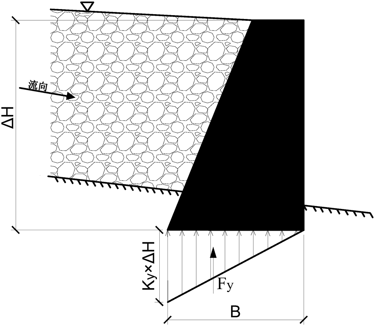
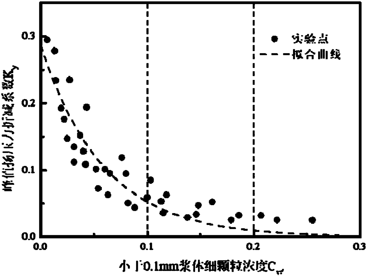
At present, the value of Ky is generally taken from 0 to 1 based on experience. The range of values ​​is too large, and no quantitative relationship with a certain factor has been established. Engin

Method used


Image

  • Calculation method for uplift pressure of dam foundation of debris flow sand dam
  • Calculation method for uplift pressure of dam foundation of debris flow sand dam
  • Calculation method for uplift pressure of dam foundation of debris flow sand dam

Examples


Embodiment 1

[0060] The present invention is applied to the uplift pressure calculation for the stability calculation of a mud-rock flow ditch sand retaining dam in the Bailongjiang River Basin.

[0061] A debris flow ditch is a first-level tributary ditch in the Bailongjiang River Basin in Gansu Province, with a drainage area of ​​12.47km 2 , the length of the main ditch is 7.84km. There have been many debris flow outbreaks in this ditch, which caused the mouth of the ditch to silt and block the river, causing serious economic losses and casualties. In order to prevent the debris flow in this ditch, several debris flow dams were built in the main ditch to block the debris flow step by step to reduce the flow rate and flow rate, while stabilizing the ditch and slope. Among them, No. 4 main dam has an altitude of 1220±5m and is a masonry gravity-type solid dam with an effective dam height of 7.6m and a crest width of 2m. 0. The dam foundation soil is gravel soil with good permeability. Th...

Embodiment 2

[0073] The present invention is applied to the calculation of uplift pressure in the structural design of a mud-rock flow ditch and sand retaining dam along the Sichuan-Tibet line.

[0074] A debris flow ditch is a typical extra-large ice cement flow ditch along the Sichuan-Tibet Railway, with a drainage area of ​​25.41km 2 , the main ditch is 7.9km long, and the average slope of the ditch bed is 381‰. The proposed Sichuan-Tibet Railway passes through this ditch. A large-scale ice and cement flow broke out in the ditch, and the debris fluid migrated outside the mountain to form a large-scale accumulation fan, blocking the main river and forming a barrier dam. In order to control the debris flow in the ditch and prevent the large-scale disaster caused by the debris flow blocking the river, it is planned to build several sand dams in the ditch to stop the debris flow. Because of its simple structure, good durability, and high blocking efficiency, the solid sand control dam can ...


PUM


Abstract

The invention provides a calculation method for the uplift pressure of the dam foundation of a debris flow sand dam. The method comprises the following steps that 1, the debris flow density is determined; 2, the percentage of the fine particle content is determined; 3, the fine particle concentration of the debris flow slurry is determined according to the debris flow density and the percentage ofthe fine particle content; 4, the reduction coefficient of the uplift pressure is calculated according to the fine particle concentration of the debris flow slurry; and 5, the uplift pressure joint force is calculated. The invention provides a method for calculating the reduction coefficient of the peak uplift pressure according to the index parameters of the debris flow property and the concentration of the fine particles of the slurry, the influencing mechanism of the debris flow density and fine particle content on the peak uplift pressure in front of the dam are taken into full consideration, compared with the traditional method of relying on artificial subjective experience to select the uplift pressure reduction coefficient, the method has a more scientific measurement principle, the calculation form is simple, the parameter acquisition is easy, and the higher engineering practical values are achieved.

Description

technical field [0001] The invention relates to a method for calculating the uplift pressure of a debris flow sand retaining dam foundation, in particular to a method for calculating the uplift pressure reduction coefficient based on the fine particle concentration of debris flow slurry in front of the dam, and belongs to the fields of measurement technology and mountain disaster prevention and control. Background technique [0002] As a key project to prevent and control debris flow, solid sand control dam has the advantages of simple structure, good durability and high blocking efficiency, and is the most widely used in debris flow control projects. The disaster prevention mechanism of the solid sand check dam is to block step by step to reduce the flow and velocity of debris flow, and at the same time, it can stabilize the ditch and slope, and raise the erosion base level. In the structural design and stability calculation of sand check dams, an important vertical load—up...

Claims


Application Information

Patent Timeline
IPC IPC(8): E02B1/00E02B3/10
CPCE02B1/00E02B3/10
Inventor 游勇张莉柳金峰孙昊刘道川刘洋袁东周文兵
Owner INST OF MOUNTAIN HAZARDS & ENVIRONMENT CHINESE ACADEMY OF SCI
Why Eureka
Try Eureka