Corrosion-resistance concrete pipe rack

A concrete and pipe gallery technology, applied in water conservancy projects, artificial islands, underwater structures, etc., can solve the problems of easy up and down dislocation and deformation of interfaces, difficult on-site construction, and corrosion of pipe gallery cables, etc., and achieve good joint water quality. The effect of sealing, improving construction efficiency and shortening construction time

Inactive Publication Date: 2018-11-06
ANHUI YUTE CONCRETE STRUCTURE TECH
View PDF5 Cites 0 Cited by
  • Summary
  • Abstract
  • Description
  • Claims
  • Application Information

AI Technical Summary

Problems solved by technology

[0002] With the expansion of urban areas and the development of construction, the advantages of building underground comprehensive pipe corridors have gradually been affirmed by relevant government departments. Independently buried electricity, telecommunication, heat, water supply, gas and other pipelines are collected and installed in a common underground pipeline corridor, and common maintenance and centralized management are implemented to reduce the impact on road traffic and environmental pollution caused by frequent excavation and buried pipelines on the road surface in the past. Problems such as the current construction of comprehensive pipe galleries are all using the traditional cast-in-place construction method, which is difficult to construct on-site, causing certain difficulties to the construction. The disadvantage of the concrete pipe gallery is that its interface is prone to dislocation and deformation due to uneven foundation settlement and other reasons, causing leakage and breakage at the interface, which leads to corrosion of cables inside the pipe gallery

Method used


Image

  • Corrosion-resistance concrete pipe rack
  • Corrosion-resistance concrete pipe rack

Examples


Embodiment Construction

[0013] The following will clearly and completely describe the technical solutions in the embodiments of the present invention with reference to the accompanying drawings in the embodiments of the present invention. Obviously, the described embodiments are only some, not all, embodiments of the present invention. Based on the embodiments of the present invention, all other embodiments obtained by persons of ordinary skill in the art without making creative efforts belong to the protection scope of the present invention.

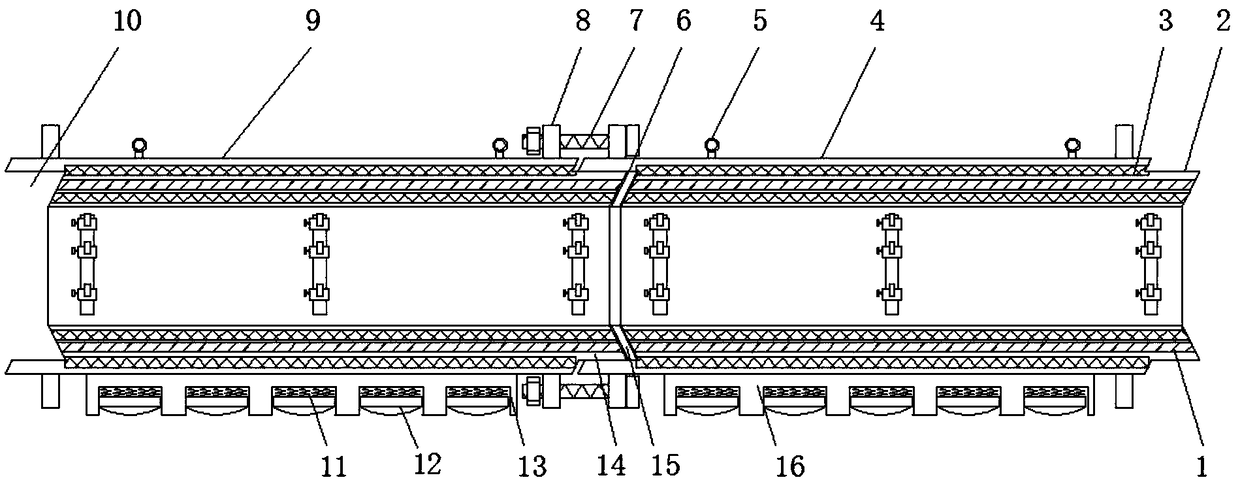
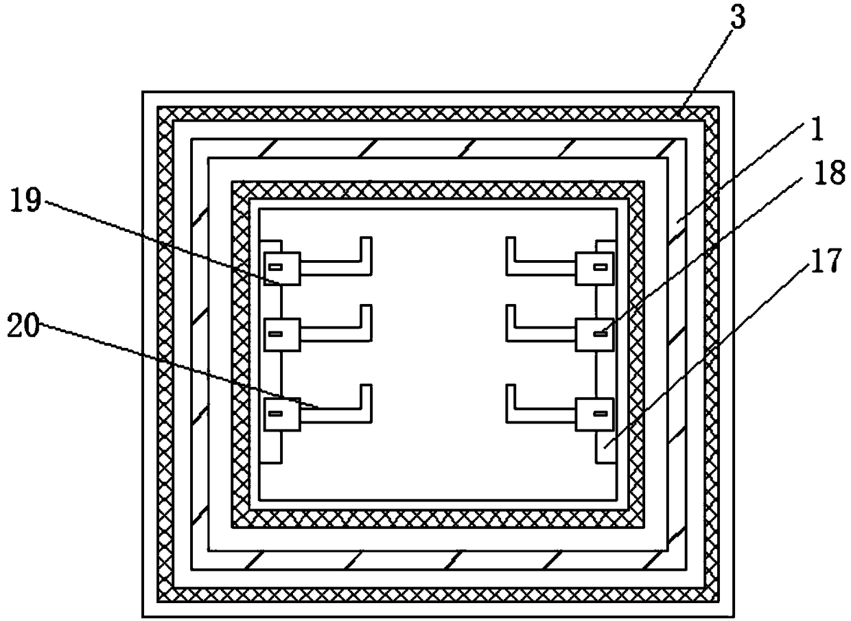
[0014] see Figure 1-2 , an embodiment provided by the present invention: an anti-corrosion concrete pipe gallery, comprising a first pipe section 4, a second pipe section 9, fiber reinforced bars 3 and an annular steel pipe 1, one end of the first pipe section 4 is provided with a first Recess 6, the other end of the first pipe joint 4 is provided with a first protrusion 2, one side of the first recess 6 is provided with a second pipe joint 9, and one end of ...


PUM


Abstract

The invention discloses a corrosion-resistance concrete pipe rack. The corrosion-resistance concrete pipe rack comprises a first pipe section, a second pipe section, a fiber reinforcement and annularsteel pipes; a first recess part is arranged at one end of the first pipe section, and a first convex part is arranged at the other end of the first pipe section; the second pipe section is arranged on one side of the first recess part; a second convex part, matched with the first recess part, is mounted at the end, near the first pipe section, of the second pipe section; a sealing ring is arranged between the second convex part and the first recess part; a second recess part, matched with the first convex part, is arranged at the other end of the second pipe section; and the annular steel pipes are mounted in the first pipe section and the second pipe section. As grooves are uniformly formed in one side of a base, and semicircular extrusion blocks are mounted in the grooves through springs, the friction force with the ground is reduced in the construction installation process, the damage of the pipe sections is prevented, meanwhile, the precipitation resistance is facilitated, and thestructural damage of the pipe rack is reduced.

Description

technical field [0001] The invention relates to the technical field of concrete pipe gallery, in particular to an anti-corrosion concrete pipe gallery. Background technique [0002] With the expansion of urban areas and the development of construction, the advantages of building underground comprehensive pipe corridors have gradually been affirmed by relevant government departments. Independently buried electricity, telecommunication, heat, water supply, gas and other pipelines are collected and installed in a common underground pipeline corridor, and common maintenance and centralized management are implemented to reduce the impact on road traffic and environmental pollution caused by frequent excavation and buried pipelines on the road surface in the past. Problems such as the current construction of comprehensive pipe galleries are all using the traditional cast-in-place construction method, which is difficult to construct on-site, causing certain difficulties to the cons...

Claims


Application Information

Patent Timeline
Patent Type & Authority Applications(China)
IPC IPC(8): E02D29/045E02D29/16
CPCE02D29/10E02D29/16
Inventor 肖吕阳
Owner ANHUI YUTE CONCRETE STRUCTURE TECH
Why Eureka
Try Eureka