Door lock structure

A door lock structure and handle technology, applied in the field of door locks, can solve the problems of lower product market competitiveness, easy durability damage, high cost, etc., and achieve the effect of improving richness and innovation, prolonging service life, and shortening service life

Active Publication Date: 2018-11-06
MIDEA INTELLIGENT LIGHTING & CONTROLS TECH CO LTD
View PDF5 Cites 1 Cited by
  • Summary
  • Abstract
  • Description
  • Claims
  • Application Information

AI Technical Summary

Problems solved by technology

The handle is directly installed on the lock body shell through the rotating shaft, and the connection becomes one. The push or pull rotation of the handle is realized through the rotating shaft. This structure is simple, but at present, various push-pull door locks of various manufacturers generally adopt this handle structure. , the products imitate each other and plagiarize each other, and the homogenization is serious
In addition, the existing handle structure is relatively simple, and the space for extension and change is limited, which is not conducive to product innovation and product line extension.
In addition, due to the long-term repeated opening / closing of the door lock during the use of the product, the moving parts of the handle and the front panel of the door lock are prone to durable damage. Once damaged, the entire handle or front panel of the door lock needs to be replaced, resulting in high maintenance costs. high
In addition, in order to prolong the service life of the door lock, it is often necessary to use materials with better structural strength for the handle and the front panel of the door lock as a whole, resulting in a high overall cost of the product and greatly reducing the market competitiveness of the product

Method used


Image

  • Door lock structure
  • Door lock structure
  • Door lock structure

Examples


Embodiment Construction

[0056] In order to have a clearer understanding of the above objects, features and advantages of the present invention, the present invention will be further described in detail below in conjunction with the accompanying drawings and specific embodiments. It should be noted that, in the case of no conflict, the embodiments of the present application and the features in the embodiments can be combined with each other.

[0057] In the following description, many specific details are set forth in order to fully understand the present invention. However, the present invention can also be implemented in other ways different from those described here. Therefore, the protection scope of the present invention is not limited by the specific details disclosed below. EXAMPLE LIMITATIONS.

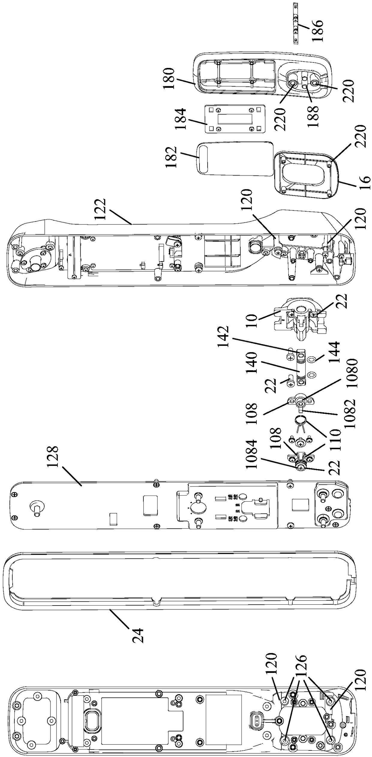
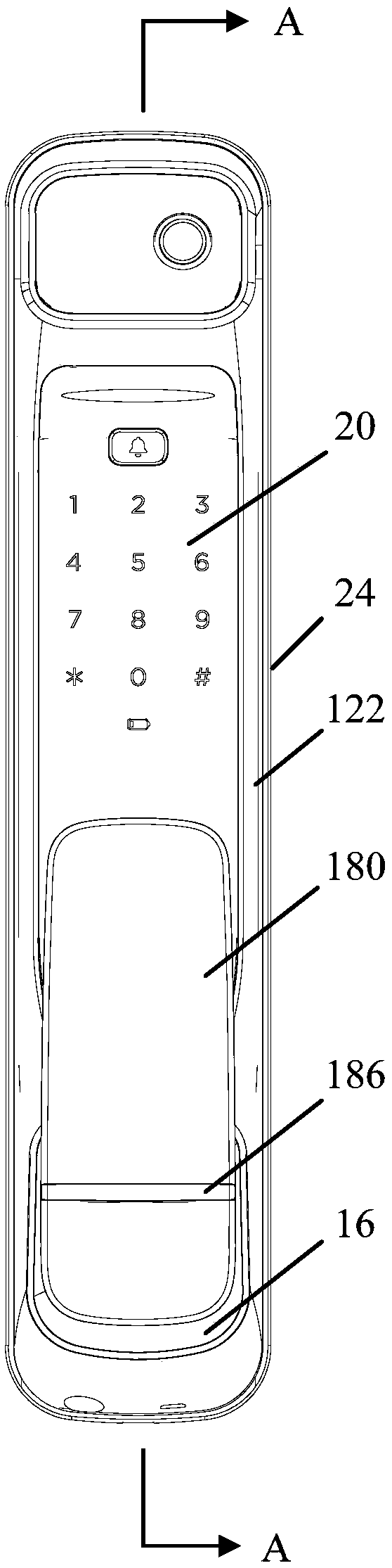
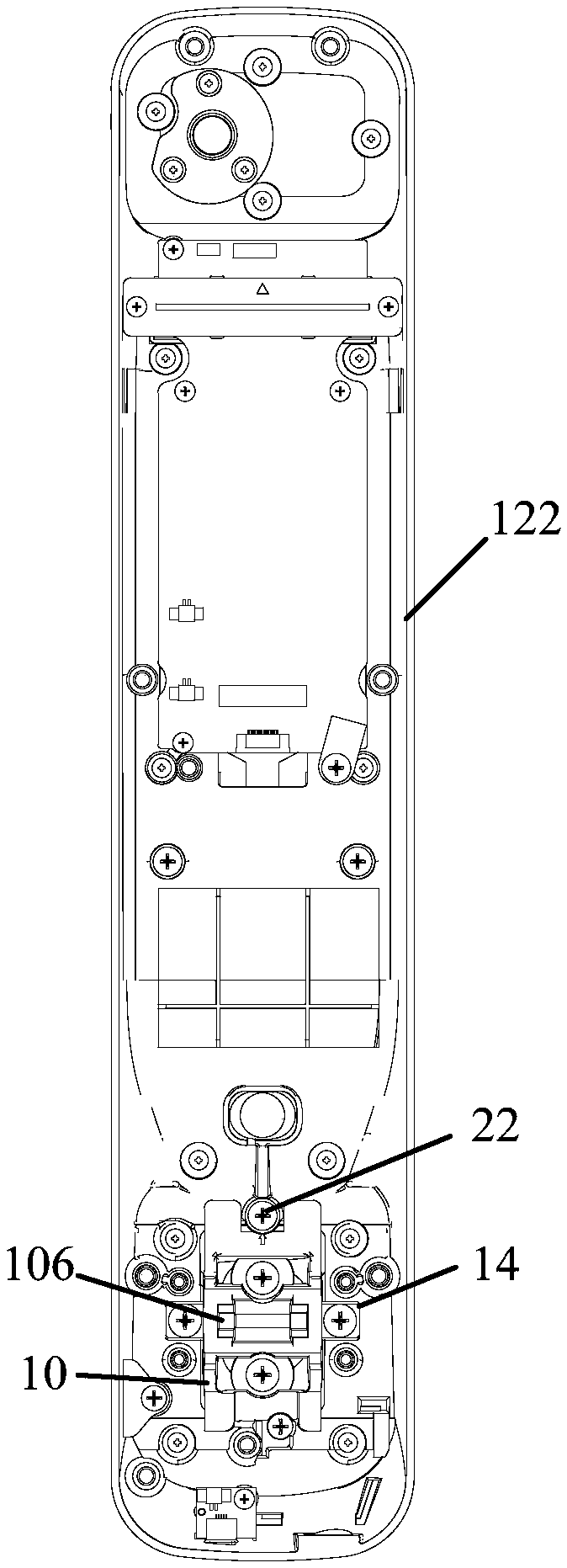
[0058] Refer below Figure 1 to Figure 25 Some embodiments according to the invention are described.

[0059] Such as Figure 1 to Figure 25 As shown, the door lock structure according to an embodim...


PUM


Abstract

The invention provides a door lock structure. The door lock structure comprises a panel assembly, a handle fixing block and a handle assembly. A containing cavity is formed in the panel assembly, wherein one side of the containing cavity is open. The handle fixing block is rotatably arranged in the containing cavity and on a plate body, wherein the plate body is provided with an opening; and the handle fixing block comprises a first limiting portion and a matching portion, wherein the matching portion extends out of the opening. The handle assembly is arranged outside the containing cavity andfixedly connected with the handle fixing block through the matching portion. Second limiting portions are fixedly arranged on the inner wall of the containing cavity. In the process that the handle assembly is stressed and rotates, the rotation space of the handle assembly is limited through matching between the first limiting portion and the second limiting portions. By means of the door lock structure, product differentiation design is achieved; structure reinforcing is conducted on key motion components such as a handle main body and the handle fixing block; in addition, materials higher in strength can be selected for producing the door lock structure, and strength of the door lock structure is improved; and damaged components can be repaired or replaced in a targeted manner, and therepair cost is remarkably lowered.

Description

technical field [0001] The present invention relates to the technical field of door locks, in particular to a door lock structure. Background technique [0002] Present push-pull door lock handle structure mainly is made up of three parts, handle, lock body shell, rotating shaft. The handle is directly installed on the lock body shell through the rotating shaft, and the connection becomes one. The push or pull rotation of the handle is realized through the rotating shaft. This structure is simple, but at present, various push-pull door locks of various manufacturers generally adopt this handle structure. , The products imitate and copy each other, and the homogenization is serious. In addition, the existing structure of the handle is relatively simple, and the space for extension and change is limited, which is not conducive to product innovation and product line extension. In addition, due to the long-term repeated opening / closing of the door lock during the use of the pr...

Claims


Application Information

Patent Timeline
Patent Type & Authority Applications(China)
IPC IPC(8): E05B3/00E05B9/00E05B1/00
CPCE05B1/00E05B3/00E05B9/002
Inventor 罗培锐
Owner MIDEA INTELLIGENT LIGHTING & CONTROLS TECH CO LTD
Why Eureka
Try Eureka